Hello everyone, a while back I posted an example on how to get the ZA6 Robot to draw SVG file paths, and at the end, I listed a few things to improve which included a pen holder.
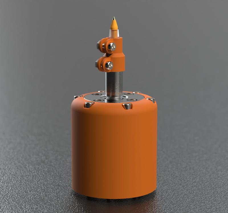
So my friend Alec and I collaborated to create the perfect pen holder for the ZA6 robot arm.

Here are the STL files:
Lower Section (2.0).STL (305.6 KB)
Pen adapter.STL (270.8 KB)
Plunger.STL (18.8 KB)
Upper Section (2.0).STL (1.4 MB)
I was unable to attach a zip file for the Solidworks project so I posted a GitHub repository where you can get all the project files which include the STLs and Solidworks files. → GitHub - zick2/za6_pen_holder_project
Here is a file that lists all the materials you need for this project
Penholder Material and Stats - V2 data.pdf (564.6 KB)
Comparison video New vs Old

This was a fun project and the first project where I had to pay too much attention to details and perfection. The main reason we created this, is to make the robot draw precise straight lines. The robot, of course, is capable of drawing straight lines but the issue was that the previous pen holder had so much wiggle room. Also, the spring distance was too short.

[Older version of the pen holder]
For the new pen holder, we had to use a linear bearing and some steel tubing that was a perfect fit to get rid of the wiggle when drawing.
Though for the tubing, get ready to sand it down a bit to make sure it glides smoothly.
The one we got was the exact size that fits the linear bearing but it had a really thin extra layer that made it hard to glide through the bearing smoothly. It shouldn’t take longer than 5 minutes to sand it down.
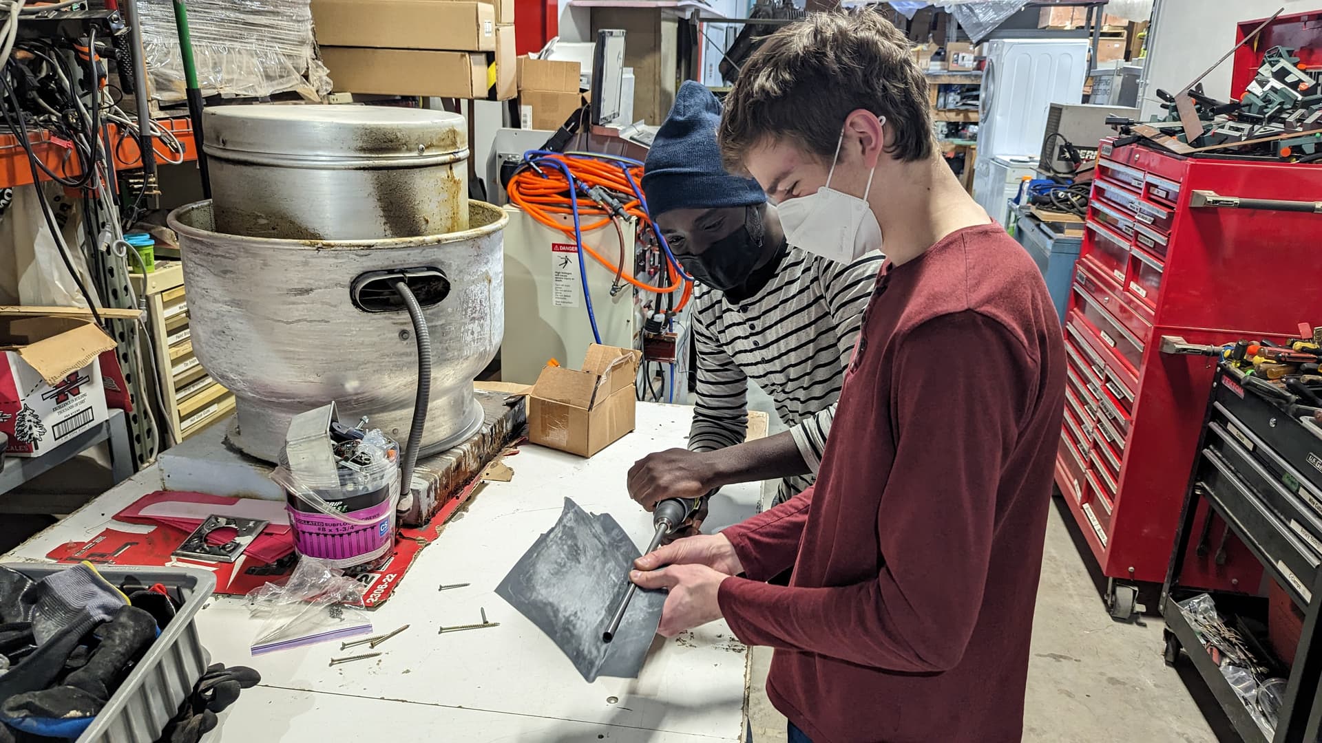
[Alec and I sanding down the tubing]
Below is an image showing the dimensions you need for the tubing to work with the pen holder
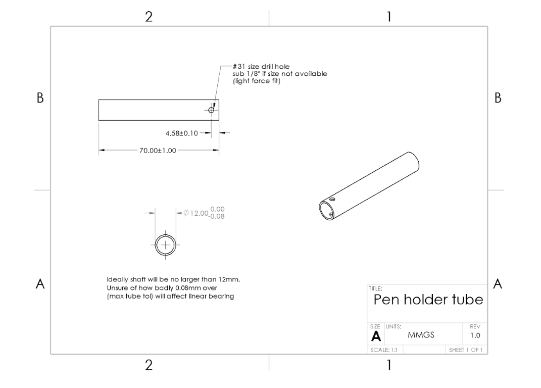
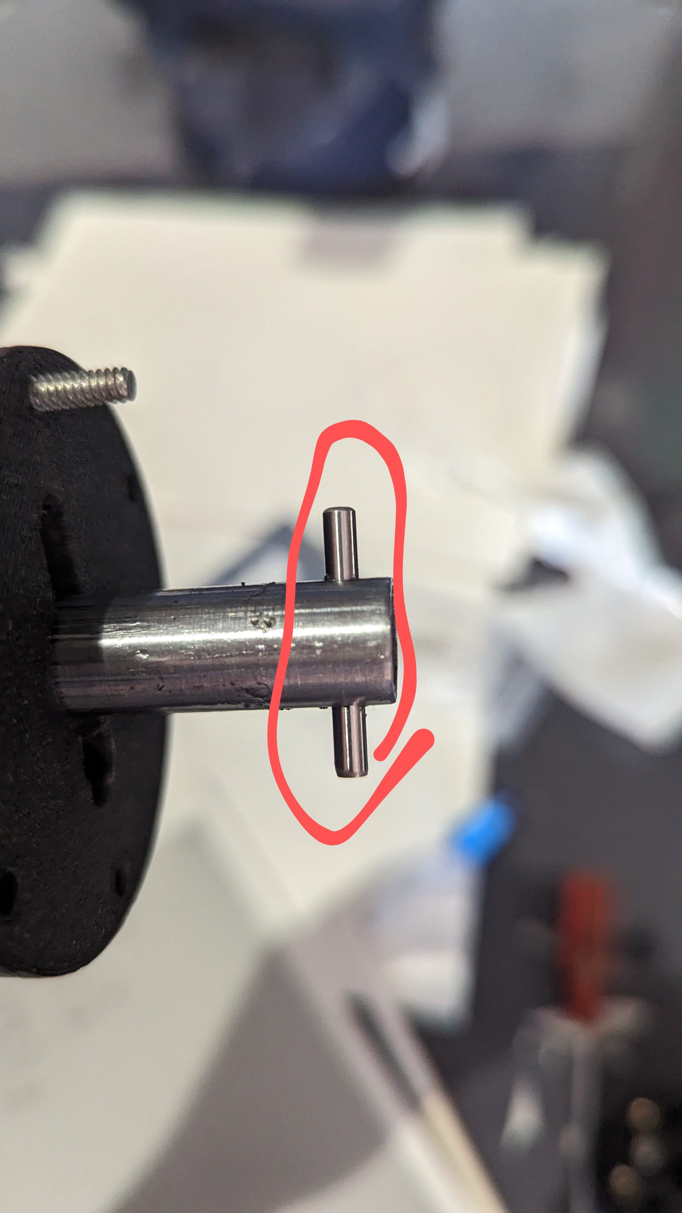
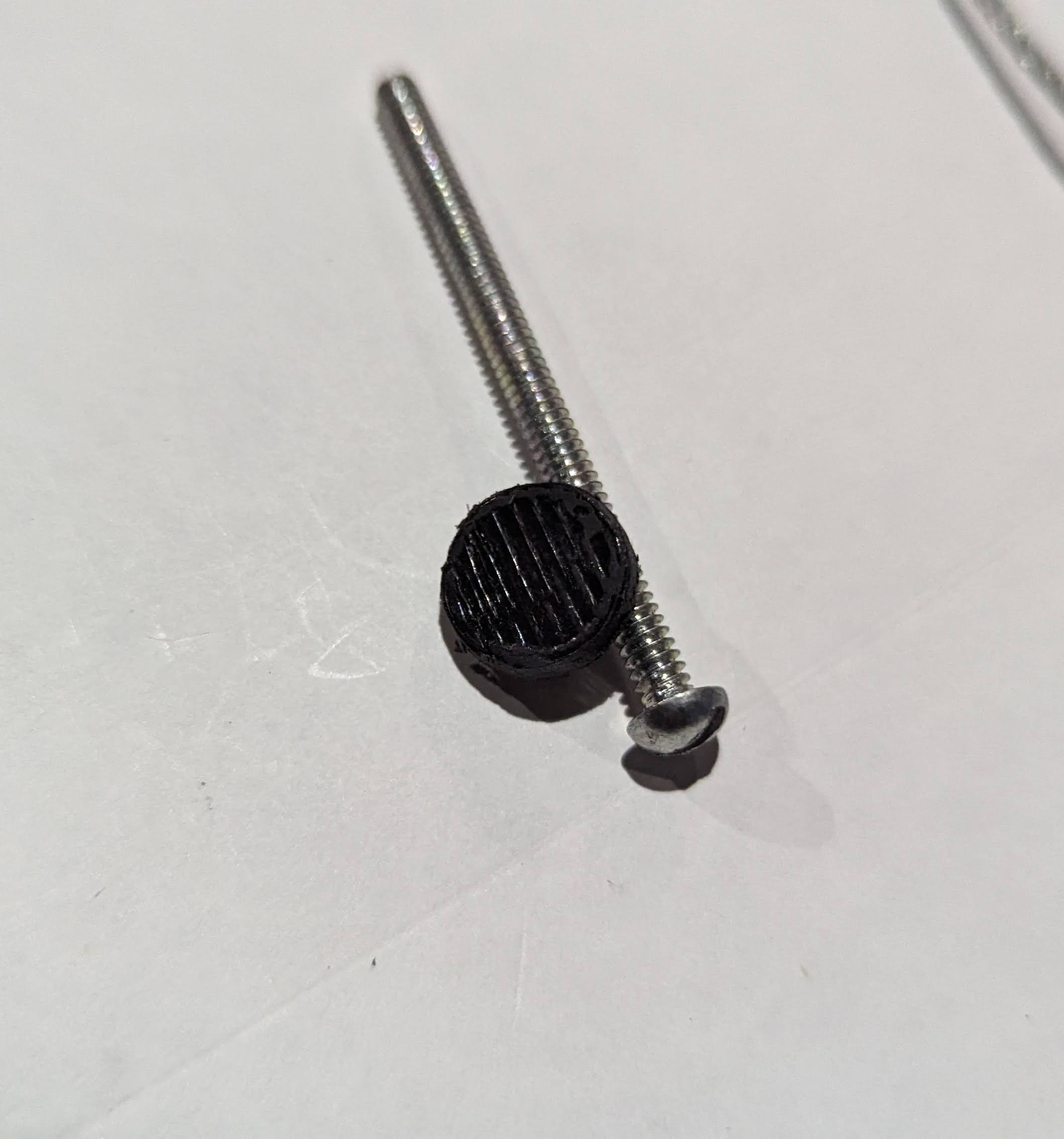
At the end of the tubing, there is a hole where a 1/8’’ by 1’’ pin goes to prevent the tube from shooting out.
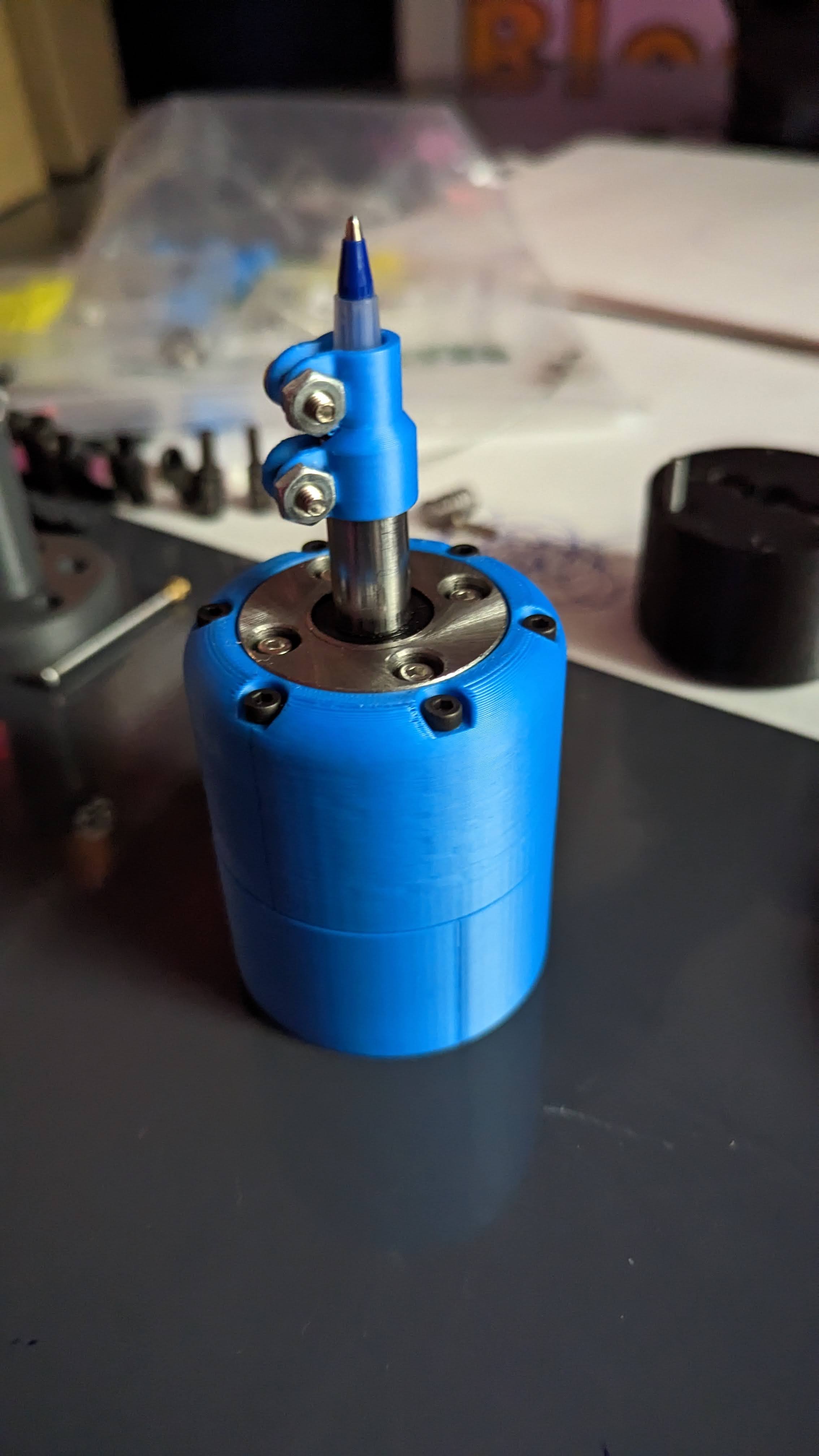
The pen holder has two parts the lower part (connects to the robot’s end effector) and the upper part. In the image, you will notice some insert nuts. You need ten in total. Six go into the lower part (for holding the upper part) and four go into the upper part (for holding the linear bearing).


[Lower part on the left and right is the upper part]
In the center that’s where the tubing goes and below that goes the spring.
Between the spring and the tubing goes the plunger.
[Plunger]
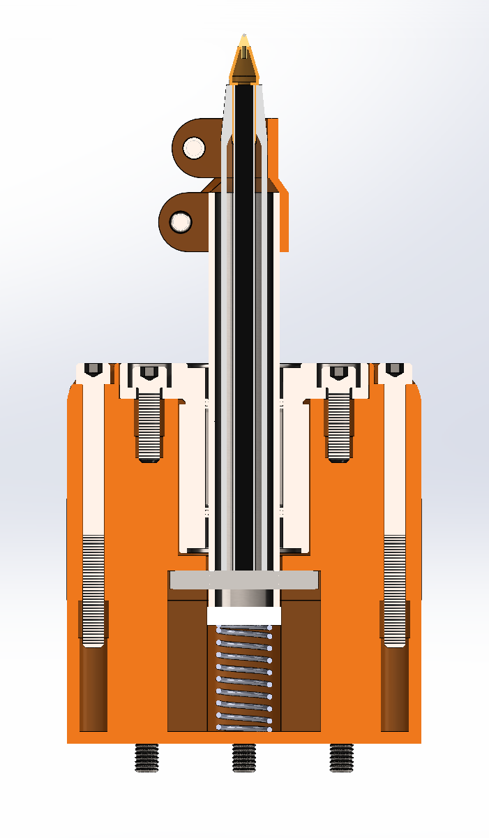
Here is a cross-section of the pen holder though it doesn’t include the insert nuts that should hold the linear bearing screws and the lower and upper part joint screws.
Thanks to Alec for helping me get this project done.
He has a more detailed journey of the whole project on his portfolio site: Tormach ZA6 pen plotter module / Alec Marshall
So far I am satisfied with the results of this project but if I had to improve on it I would try to make it easy to install on the robot. Currently, it’s a bit of a journey to install or uninstall which might be terrible for some people. This is my next goal to achieve but if anyone beats me to it feel free to share I would like to see how you did it.