This example shows how to get the ZA6 Robot arm to draw SVG paths with the help of svgpathtools python library. This library has a collection of tools that you can use to deal with SVG paths.
The goal here is to give a script an SVG file and then it will command the robot arm to move based on the paths in that SVG file.
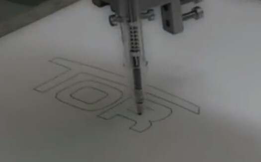
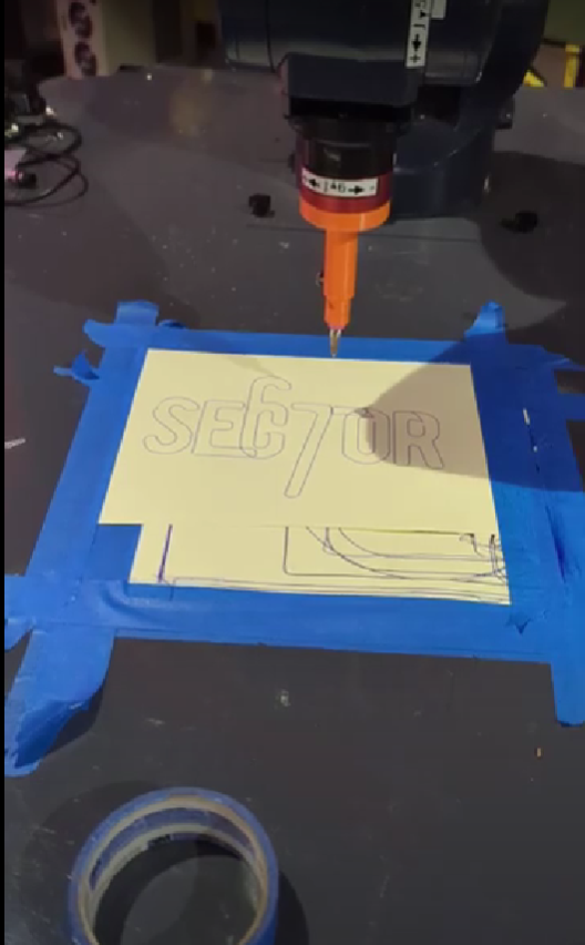
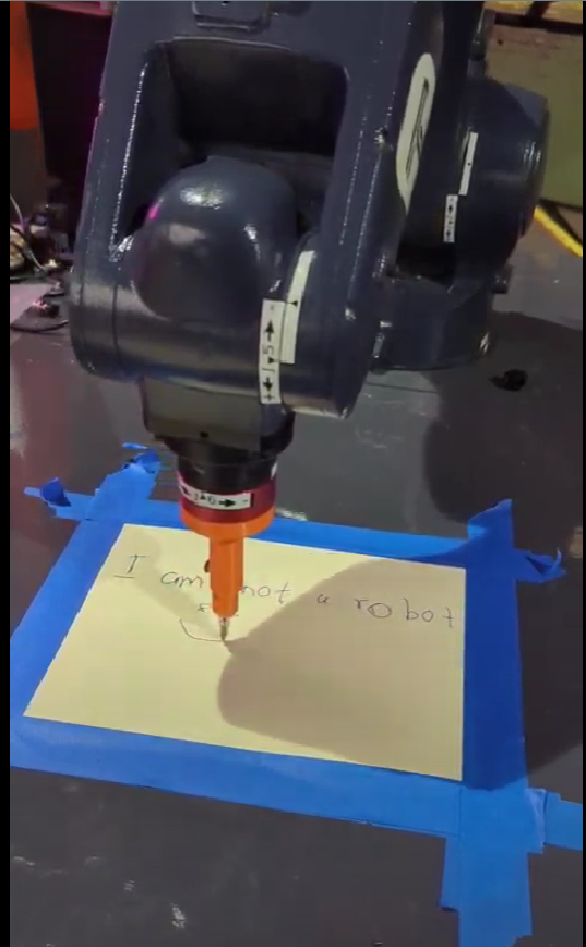
The links below will take you to the videos that show the robot in action. I added some images to act as thumbnails. ![]()
https://photos.app.goo.gl/ukW7ZBhzKSNFpdPAA
https://photos.app.goo.gl/UE5WHc9uC15VSS1FA
To get started you will need some SVG test files. I have some ready for you.
For some reason, the forum text editor didn’t allow me to upload SVG files so I just created sharable links for the files. The images you see are just png files that I uploaded(since that’s what the forum text editor accepted) to show what you will see in the SVG file but below them is the link to the actual SVG file.
b.svg file link
If you plan on creating your own SVG files I highly recommend using Inksacpe. Also, use a 600x600px canvas in Inkscape or whatever software you plan to use. This will make sure that your paths are limited in a way that the robot arm won’t accidentally swing too far to harm you or anyone.
Once you have the file assets let’s get into the code.
I might have gone overboard with the code comments but it’s mainly for those that might not be familiar with Python or coding in general.
'''
SVG Drawer
This example shows how to get the ZA6 robot arm to draw SVG paths.
To get this to work we will be using svgpathtools library. It's a great collection of tools that make it easy to play with SVG files.

NOTE: For this project Make sure you set up a user frame to make sure it supports the tool you choose to use. Here is a link on how to get this set up [https://www.youtube.com/watch?v=i_zQoZG7DYQ]

Libraries used:
svgpathtools: https://github.com/mathandy/svgpathtools
Reference:
Gerry W Jenkins has a great tutorial on how to play with SVG paths in python https://gjenkinsedu.com/post/drawing_py_svg_path_0001/
'''
from robot_command.rpl import *

try:
   #import svgpathtools that will be helping us read paths from an SVG file
   from svgpathtools import Path, Line, QuadraticBezier, CubicBezier, Arc, svg2paths
   import pygame

except:
    notify("Installing package")
    #In case the library doesn't exist we install it. (NOTE: Make sure the computer has access to the internet)
    import sh
    with sh.sudo:
        sh.pip3.install("svgpathtools")
    from svgpathtools import Path, Line, QuadraticBezier, CubicBezier, Arc, svg2paths


set_units("mm", "deg")
fname = 'b.svg'
paths, attributes = svg2paths(fname)
#Adjust path_steps or scale if something weird is happening
path_steps = 100 # Adjust accordingly if paths look weird or incomplete.
scale = 0.3  # This value is multiplied by each point of the path to make it bigger or smaller. Adjust this value if the figure looks small or big


c_paths = [] # We will store our paths here
for path in paths:
    path_points = []
    for i in range(0, path_steps+1):
        f = i/path_steps  # Remaping 0 - (path_steps) to 0.0 to 1.0
        complex_point = path.point(f)  # path.point(t) returns point at 0.0 <= t <= 1.0
        path_points.append((complex_point.real*scale, complex_point.imag*scale)) # Add extracted point to points[] list
    c_paths.append(path_points) # Add extracted points in path_points list to c_paths[] list

safeHeight = -50
def start():
    movel(p[0 , 0, safeHeight, 0, 0, 0]) # Before drawing move up to the origin at a safe height
    '''
    Since SVG paths have so many points to draw, it will make the robot arm draw the paths in an incremental manner.
    To make the robot arm draw a path in a smooth manner, we will need to blend the path points using the set_path_blending() function.
    '''
    set_path_blending(True, 0.0) # We enable path blending by passing in True for the first parameter. The next parameter is the blend radius between moves (for now it's 0.0)

    for c_path in c_paths: # For each path in c_paths
        #create variables to hold x, y coodinate points
        lx = 0
        ly = 0

        for pt in c_path: # for each point in c_path
            #Get points
            lx = pt[0]
            ly = pt[1]
            movel(p[lx, ly, 0, 0, 0, 0]) # Move pen to (lx, ly) point using the movel() function
        # After each path
        movel(p[lx, ly, safeHeight, 0, 0, 0]) #At the last point of the path move up to a safe height
    sync() # To force the execution of queued move commands
    set_path_blending(False) # Disable path blending


def main():
    change_user_frame("svg_frame") # Just to make sure that the robot uses the right user frame (NOTE: Don't forget to set up your user frame, if you don't know how to here is a great video that will get you up to speed [https://www.youtube.com/watch?v=i_zQoZG7DYQ])
    start()
Sometimes you might want to preview the SVG file path pattern using the same code that will be run by the robot arm but without the need for the robot arm. So I wrote a separate piece of code that you can run right away on your computer before you transfer your files to the robot arm computer.
This code is similar to the one above but the only difference is that instead of the robotic arm we will be using pygame python library to create a canvas for us to draw our SVG paths.
'''
SVG Drawer
This example shows how to draw SVG paths.
To get this to work we will be using svgpathtools library. It's a great collection of tools that make it easy to deal with SVG files.

NOTE: For this project make sure you set up a user frame to make sure it supports the tool that you choose to attach.

Libraries used:
svgpathtools (https://github.com/mathandy/svgpathtools)
pygame (https://www.pygame.org/docs/ref/draw.html)

Reference:
Gerry W Jenkins has a great tutorial on how to play with SVG paths in python, https://gjenkinsedu.com/post/drawing_py_svg_path_0001/
'''

import pygame
from svgpathtools import  svg2paths #Other tools that you can import from svgpathtools: Path, Line, QuadraticBezier, CubicBezier, Arc,

'''
Step 1) Setting up svgpathtools to deal with SVG paths
'''

paths, attributes = svg2paths('assets/mrT_text.svg') # Getting paths and attributes
path_steps = 100 # Number of steps to take in a path
scale = 1
c_paths = []

for path in paths:
    path_points = []
    for i in range(0, path_steps + 1): # loop from 0 to path_steps + 1
        p = i / path_steps             # Remapping 0 - path_steps(100) to  0.0 to 1.0
        complex_point = path.point(p)  # path.point(p) returns point at 0.0 <= p <= 1.0
        path_points.append((complex_point.real * scale, complex_point.imag * scale))    # Adding extracted points to path_point[] list
    c_paths.append(path_points)     # Adding collected path points to c_paths[] list

'''
Step 2) Setting up pygame to display our paths
'''

pygame.init()                                  # init pygame
surface = pygame.display.set_mode((600, 600))   # get surface to draw on (width = 600, height = 600)
surface.fill(pygame.Color('white'))            # set background to white

for c_path in c_paths: # for every path  in c_paths[] list
    pygame.draw.aalines(surface, pygame.Color('blue'), False, c_path)  # False is no closing (Meaning a closing line wont be drawn from the last point to the first)
    pygame.display.update() # copy surface to display


while True:  # loop to wait till window closes
    for event in pygame.event.get():
        if event.type == pygame.QUIT:
            exit()
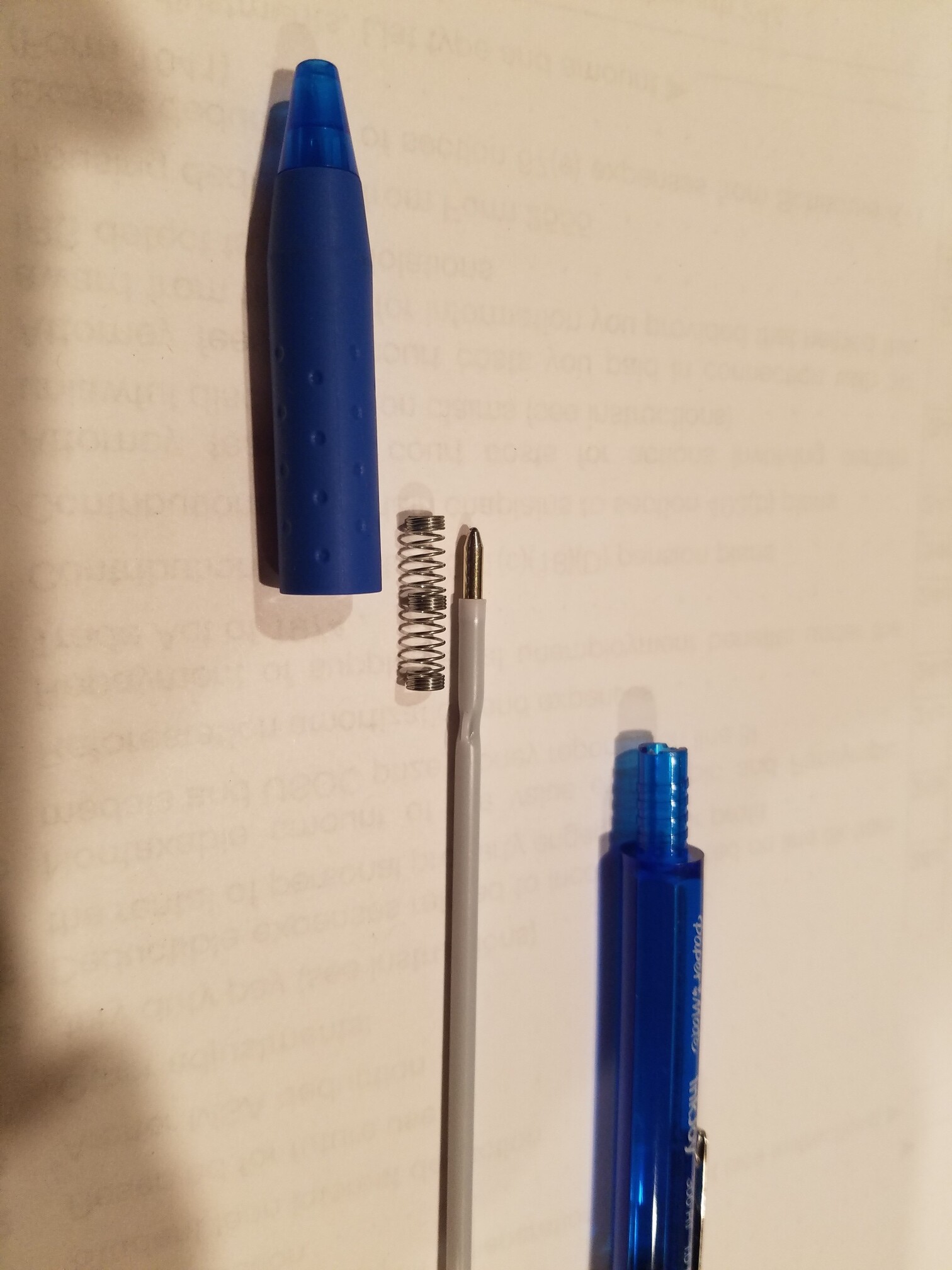
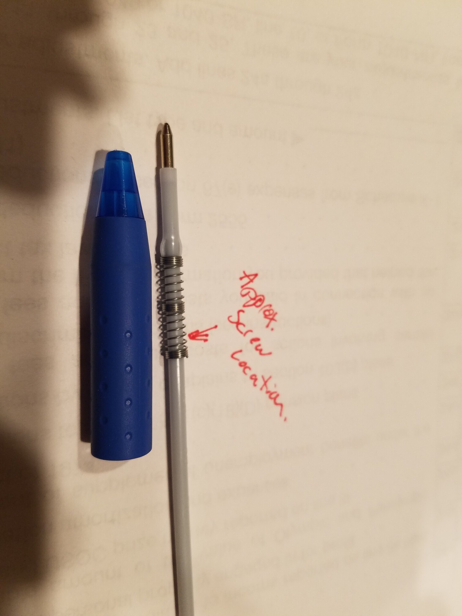
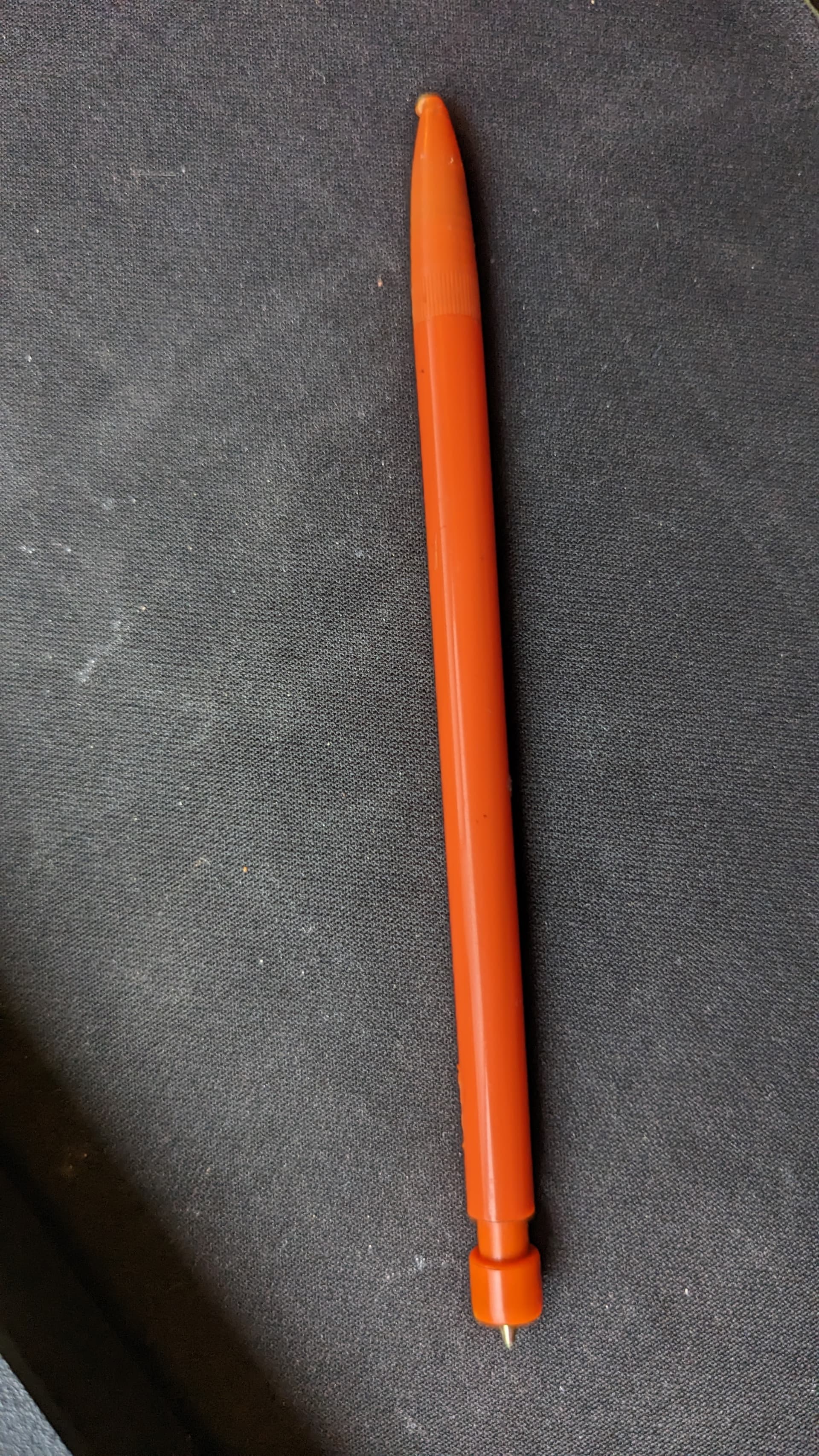
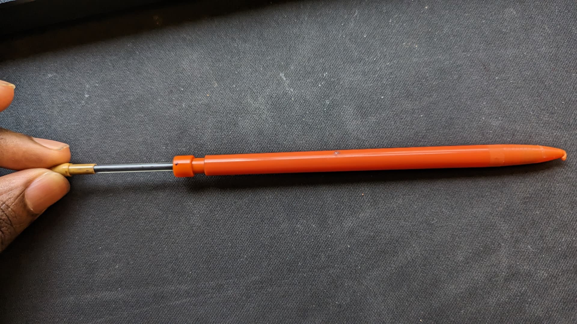
This project was fun to do and there are a few things that I plan to improve in the future. These things include; a pen holder, and using a camera hooked up directly to the robotic arm computer.
-
For those that will get a chance to try this project out you will notice that if you don’t have a good pen holder the pressure between the robot arm and the paper is really strong which punched holes in the paper. Also, the wiggle of the pen leads to imperfect lines. So making a pen holder that has good soft touch on paper is on my ToDo list.
-
It’s very tedious to move back and forth between Inkscape, script, and robot arm. So it will be nice to just have the camera take images and feed them directly to the script and convert the images into custom paths or SVG paths that the robot can follow.
If anyone beats me to these goals please let me know, I would like to see your approach