I recently purchased an 1100 PCNC for a small business that we are buying. This is not a CNC business to be clear, but rather, the CNC will be producing some of our parts that we assemble. All of our parts are plastic, so they are relatively easy to machine.
What I am really (and I mean really) struggling with is integrating the 4th axis into my Fusion 360 setup. I have the older 4th Axis (6” motorized table PN 30290), but it is brand new. I have searched and searched on how to get this to work. For example: under “Setup”, it asks for machine. If I select my Tormach, it obviously does not allow me to “turn.” If, under “Operation Type,” I select “Turning or Mill/Turn”, I get a “All Machines Hidden By Filters” message.
I have watched numerous videos (that is pretty much all I have done today), and it seems that most of them are just old enough that whatever option/button the YouTuber chooses is either no longer there in the latest Fusion or it has moved to the deep reaches of the universe. I have tried to watch some of SMW videos, but again, they are old and he talks and moves so fast that quite frankly are hard to follow.
I know that this is a comprehensive “HELP”, but if someone could point me in the right direction, that would be great. Heck, I was even using AI today (I use it frequently), and she was telling me to do this… and I would look for what she was referring to and couldn’t find it. I would take a screenshot and post it, and her response was “Oh, they have updated Fusion, and that is no longer there.” Well, no kidding. LOL
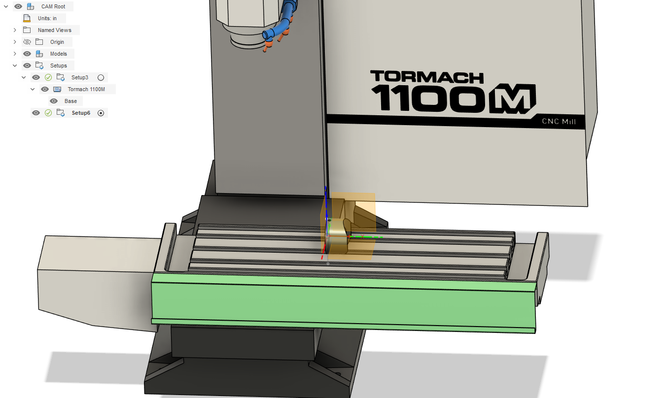
Nothing with selecting a machine is required to post a program, I’ve never set it up. Anything related to 4th axis is done with “milling”. The main thing is selecting the orientation of Z correctly so that A0 matches between the machine and Fusion, if needed, select the “tool orientation” box in your toolpaths.
Despite the name, you aren’t doing Turning (that’s lathes) or Mill-Turning (that’s specialized Mill-Turn machines), you’re doing 4th axis Milling.
One other problem is Fusion made a lot of the fancier 4th axis CNC a $$$ paid add-on not too long ago (they do this kind of thing all the time which is a great way to piss off your longtime users), but, assuming you have a paid Fusion (IDK if the free version has any CNC milling at all anymore), then you can do 4th axis indexing by setting the tool orientation per operation (which moves the 4th, not the tool, so think of it as ‘part orientation relative to the tool’).
On the Tool Orientation tab you pick a new WCS, usually with Z perpendicular to the feature you want to mill. Until you get the hang of it, setting your WCS to be the centerline of the 4th is highly advisable.
I think there’s still some basic 4th profiling you can still do as well but haven’t messed with that in a while.
Thank you, folks, for the replies so far. I really appreciate it.
I do have the paid version of Fusion, but not the highest tier. I believe it will do all of the operations that I need.
Not setting it up as a Mill-Turning operation does make sense. Thank you.
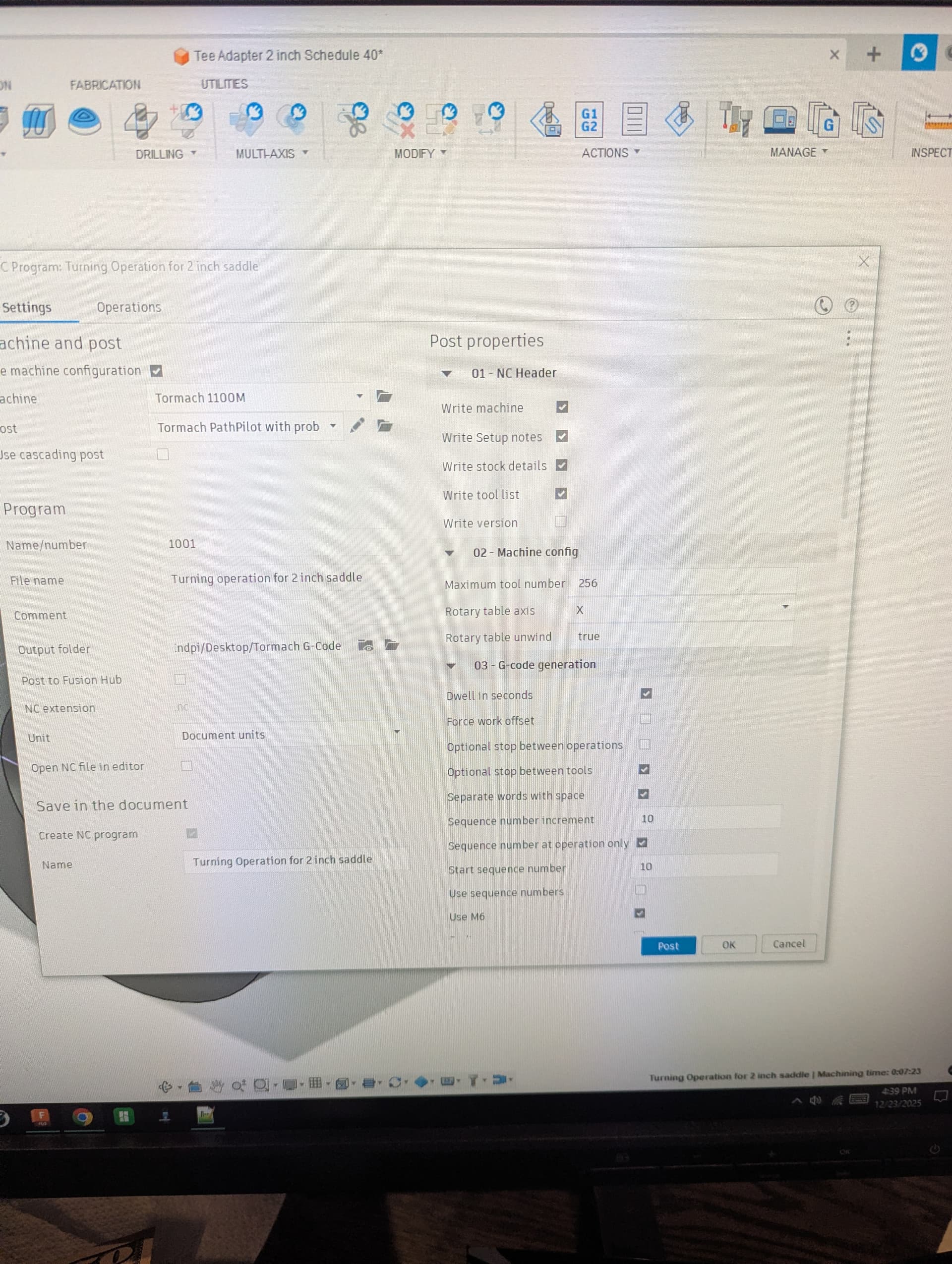
I believe I downloaded the Zoomspeed post-processor, but I will need to verify that it is the case.
I have a number of other questions about axis alignment on the part and how to do only part of the milling operation (the concave feature) before turning the part 180 degrees and duplicating the process.
Unfortunately, I will be gone for most of the day but will check back in later on. Thank you again guys for all of your help. I normally don’t struggle this much with tech, but for some reason, this is kicking my butt.
Cutting some, rotating and cutting the other side then going back is easily doable in fusion– it will move the A axis to wherever you tell it to per operation, so you can do some cutting here, then do something at 180 degrees and then come back to finish the first thing.
Ok. Dumb question but I believe I may be lacking some basic understanding which is why I am getting tripped up.
When I go to the Manufacture workspace, is this one setup with different operations within it, or is the movement along the A-axis, for example, a separate setup?
What would be the best operation for removing material from the concave cut ( 2D Adaptive, 3D Adaptive Clearing)?
Where is the A-axis movement defined? What operation and do I need additional planes to define that?
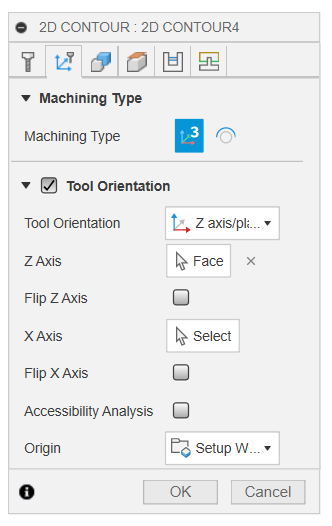
The actual “go here to make this cut” for indexing is setup per-operation. Here’s a contour cut on a part at 90 degrees– All I did was pick the new Z-axis (in this case another face that is perpendicular to the cut)/plane and Fusion (I use the Tormach post) outputs the G0 A90 before the cut begins.
As for your cut, its going to depend a lot on the size of the part and available tools and desired accuracy and surface finish. The quick way would be a contour with a long enough and large enough endmill at full depth. Put in some roughing passes if needed. But.. that may not be feasable or desireable for a lot of reasons…. and, if that’s all there is to the part and you need to bang them out, you might not even want to make it in a 4th axis.
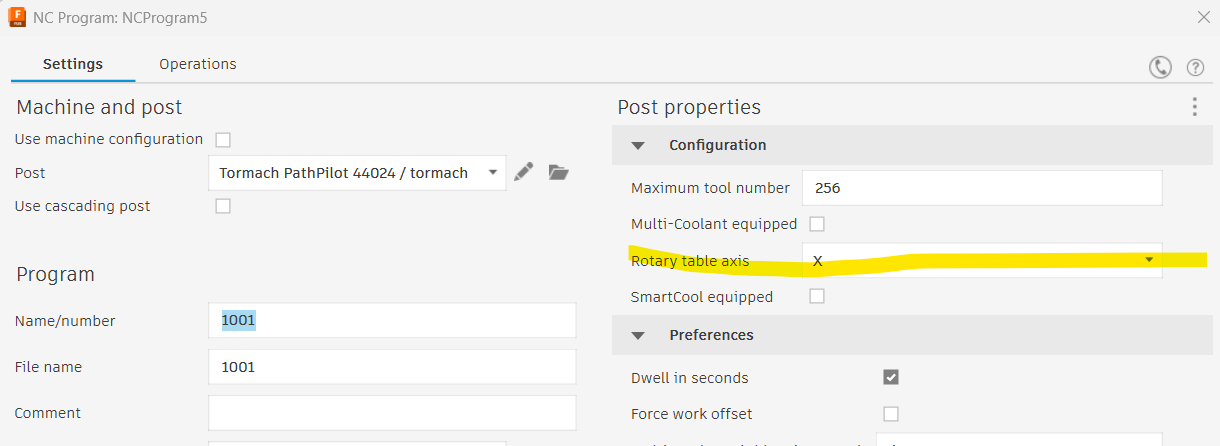
I just noticed on the PathPilot Settings page that there is a 4th axis rotary page. I do not have a probe but it seems to think that I have a probe hooked up because the “accessory Input” is lit up. I have not done a power cycle on it yet (working on it last night, having my required coffee this morning ), so it has not been powered on yet.
Question is.. do I need to utilize that setup page? Can I just use my Haimer to determine fixture points (chuck on the 4th-axis for example)for my X,Y & Z axis?
Maybe I should invest in a probe? Also thinking about a fixture plate too, just because I have numerous setups for the business that I will need to repeat on a regular basis.
If the probe is checked and set to passive (n/c) I think the light stays on assuming the triggers are in a closed state. Or you have an ETs that is n/c The accessory ports are wired together so that if you have a probe and a tool setter one has to be passive and one active. At least on the 1100mx like I have. Check your machine specs for the accessory setup.
It’s a good question about the probing setup though. I have also wondered if the A, B, C tip centering screen is used in the calculations or if it is just for centering the probe tip and disregarded for anything else.
@Neil_Gardner you don’t need the Probe to run the 4th axis or fixtures but it does speed things up a bit.
The 4th axis setup page only impacts the tool path preview and is not strictly necessary. That said, the preview can look pretty wild if you are doing synchronous work and don’t configure it.
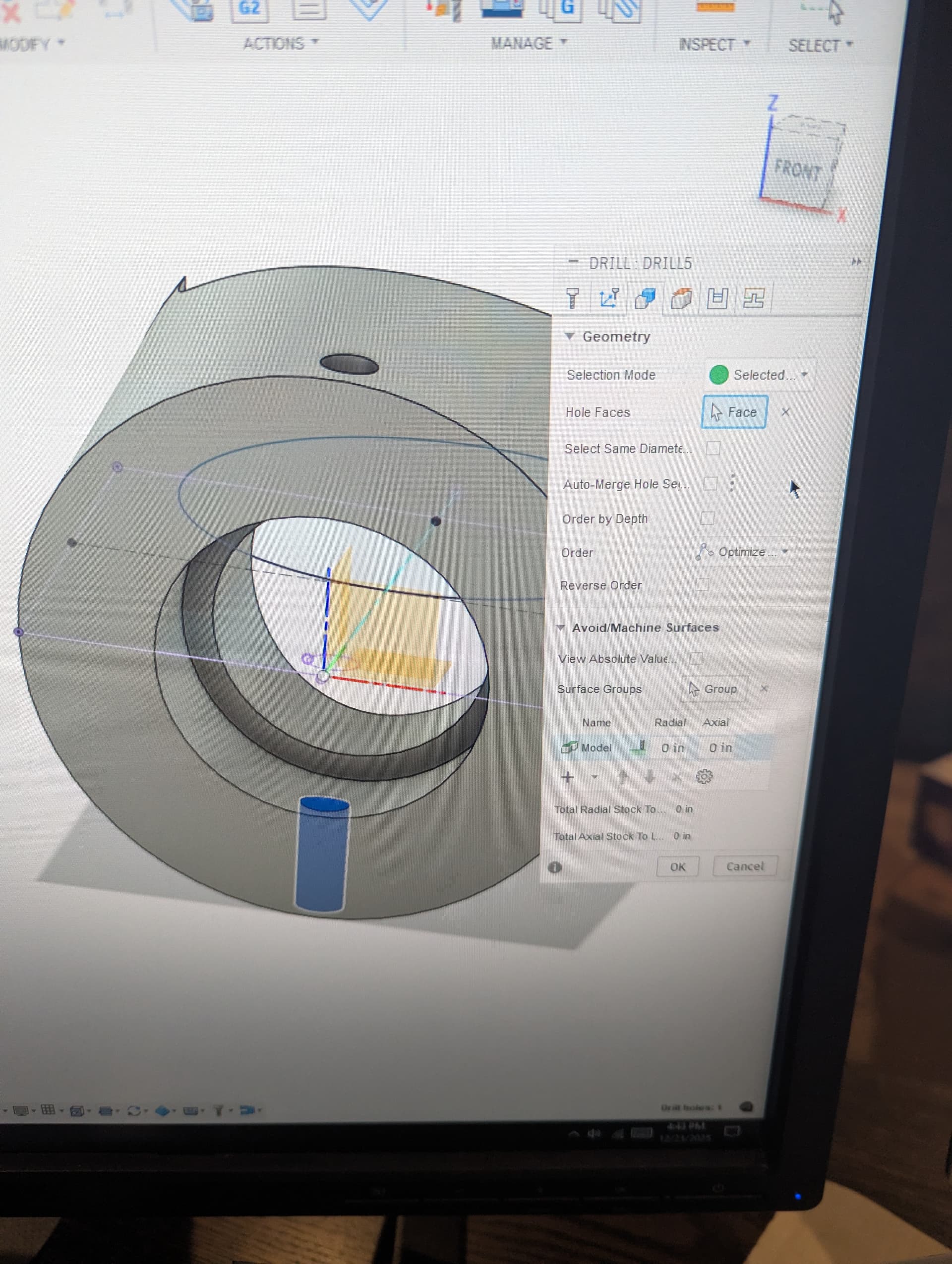
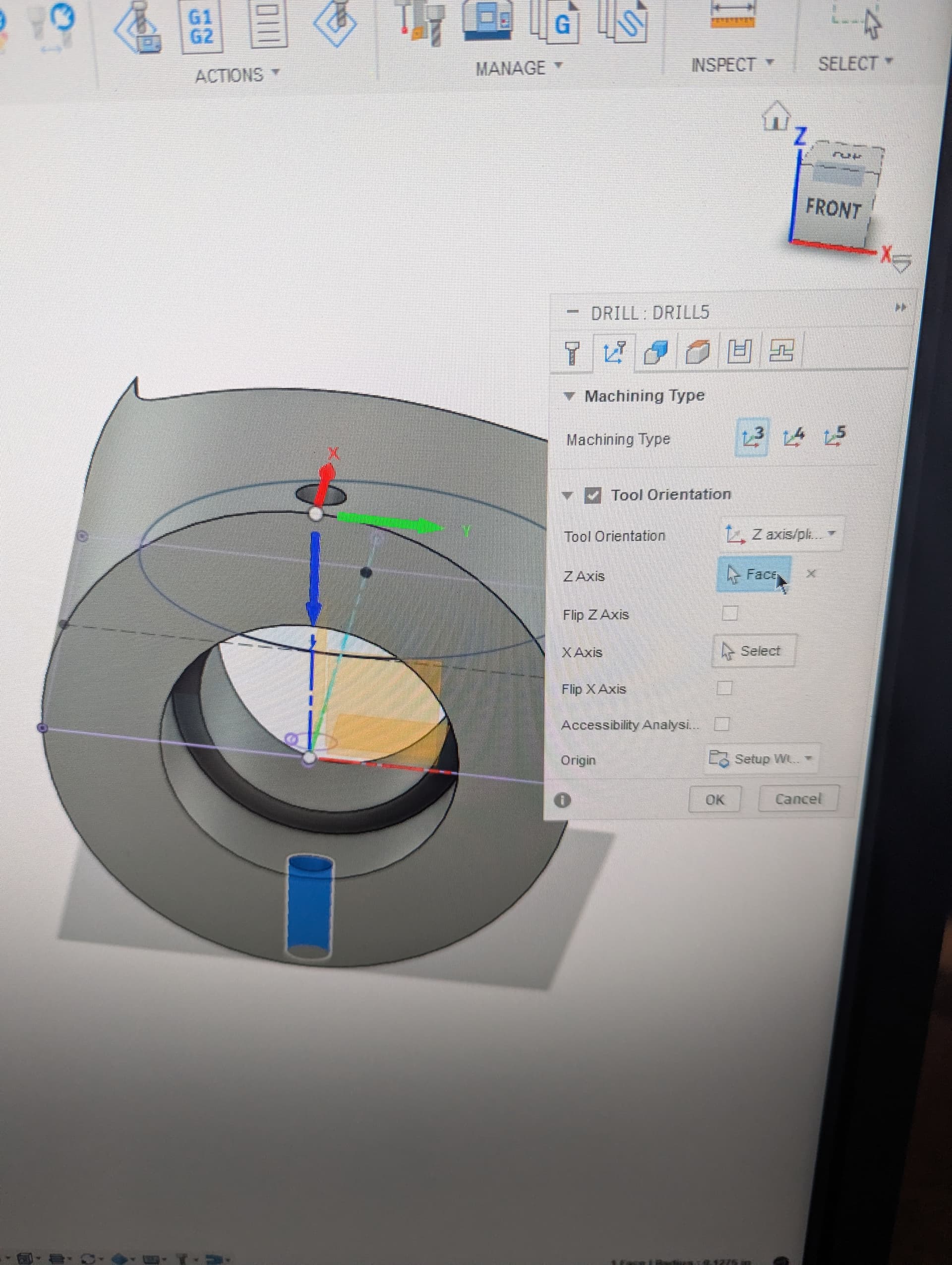
I’m sure there are better answers to your question on how to cut the concave feature, but my first solution would be to just use the 2d bore toolpath. If the size of the part is too large to take it all in one pass (plus a finish cut?), you can just run it with radial stock to leave (Passes tab?) then run it again, or configure “multiple passes”. Of course, you would want to be sure that the Z orientation is correct under the Machining Type tab.
You could also probably use the 2d contour and just pick that bottom edge. Then you’d want to check the Ramp box (same tab as lead-in-lead-out), but the same strategy would apply as far as multiple passes.
I have the 8” big brother to the 4th you have and used it for only a couple jobs in 8 years. The only configurations you have to do are all in Fusion (besides plugging it in )
Could just program a pocket in conversational. The only hard part will be setting up the center of the circular pocket. But since you have it modeled in fusion you should be able to get the coordinate pretty easy.
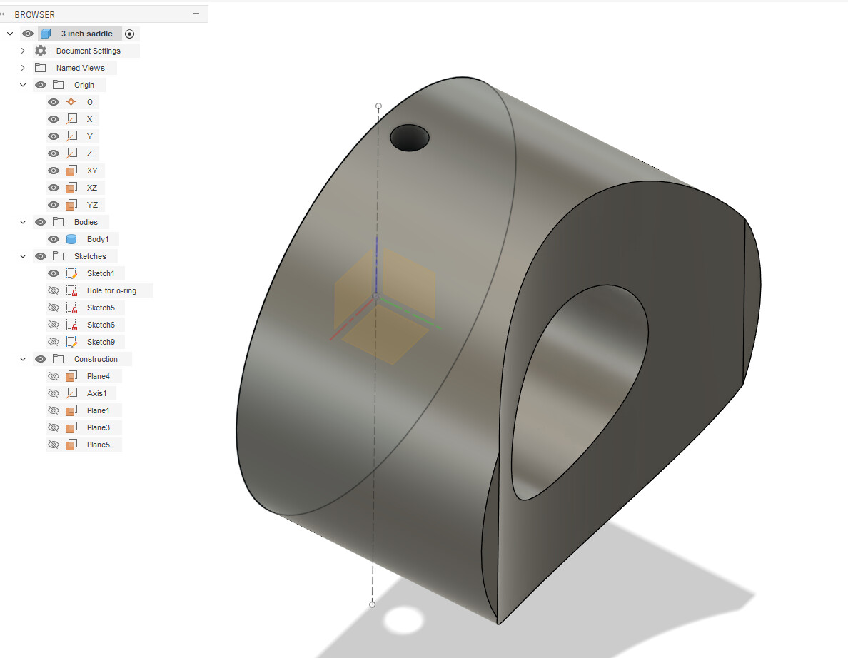
I ended up using the file I received from the current business owner, though it needed a lot of rework. It uses Sin and Cos, along with I and J coordinates, to trace the arc. The problem was that his machine (a very old, cobbled-together Light Machines brand) had different machine coordinates than mine. It was just a matter of going through it line by line and changing coordinates. Having this work in Fusion, though, would be SO much better, especially for future changes. There are at least 15 variations of the part I posted at the beginning of this thread.
But even though I can apparently get this to work by hand-coding it, that is, of course, not the preferred method when I have Fusion sitting here. All you folks do work that is significantly more complex than these parts of mine, so I know that I am just missing a few key setup points.
I am hoping that if I spend some time messing with this that it will come to me. Actually, it is imperative that this works because of the number of variations of that saddle. Also, more importantly, I just need to figure this out for future uses.
I used to fly a business jet around the Western hemisphere… I should be able to figure this out
I am finally getting the hang of setting everything up. I have run a number of successful parts, but…
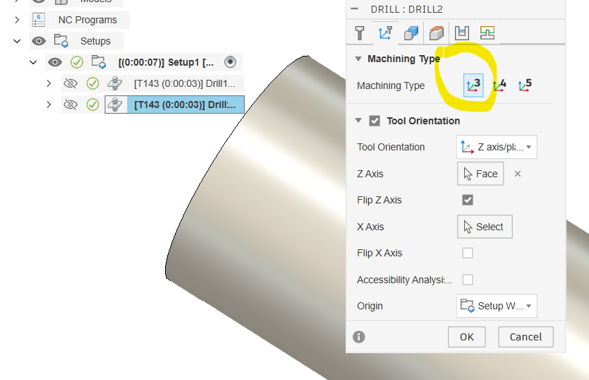
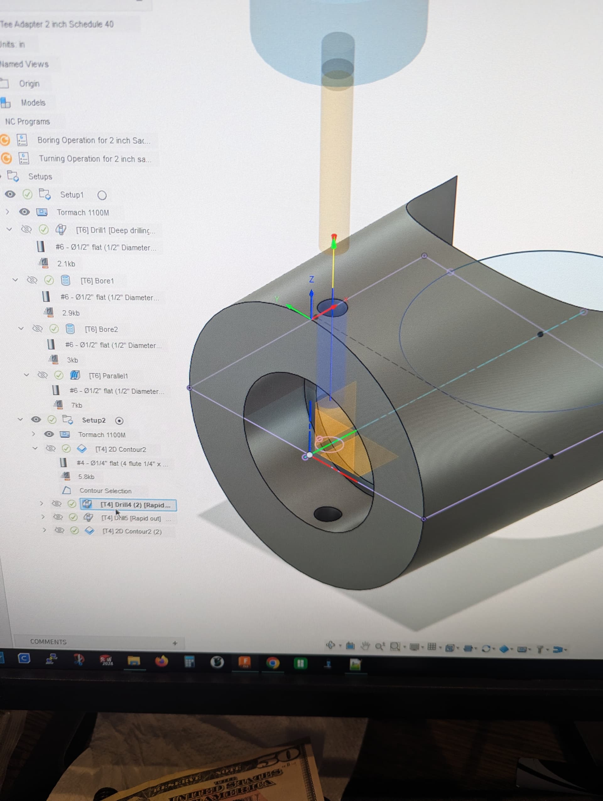
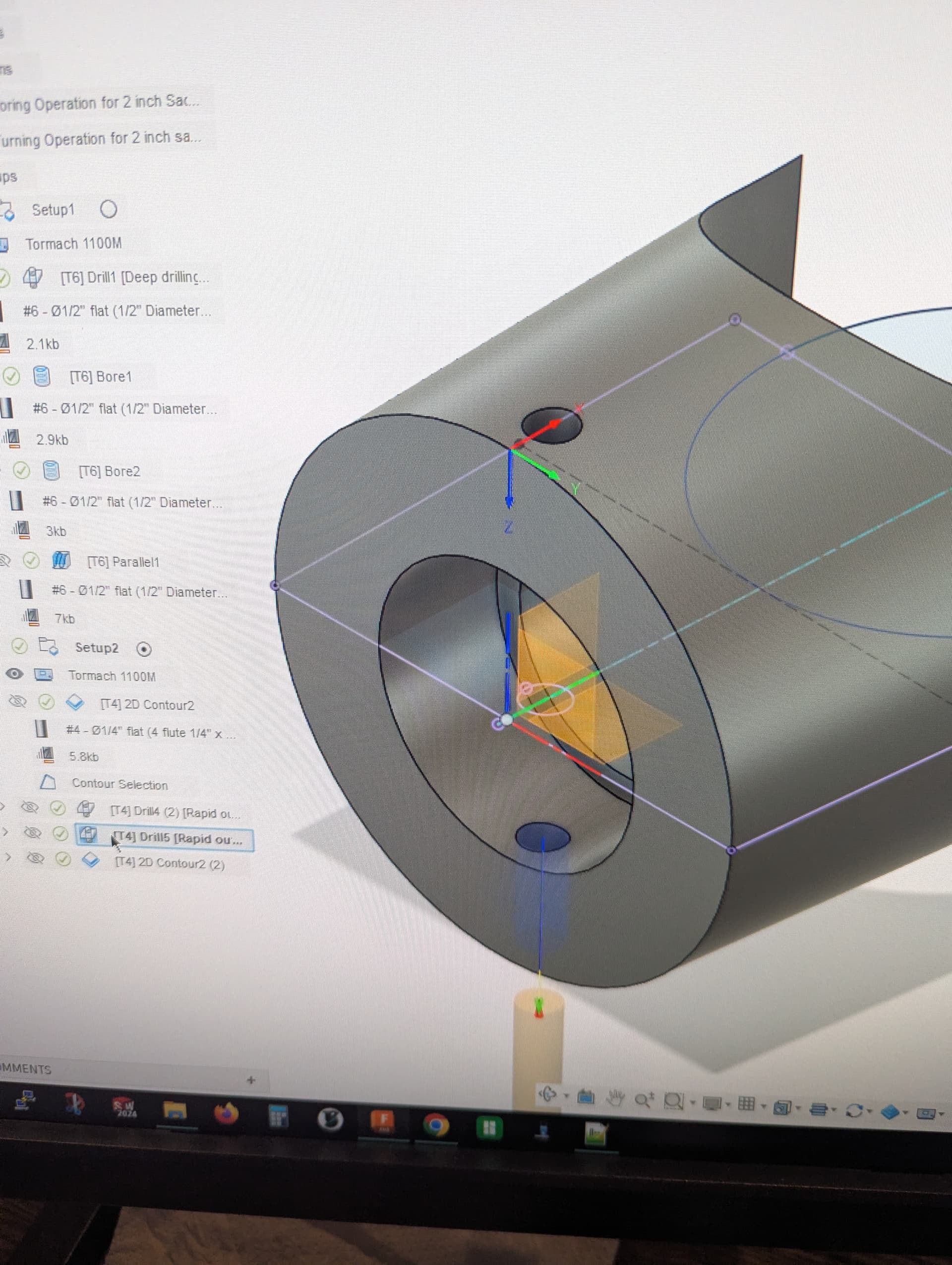
I am back to trying to set up the 4th axis in Fusion 360. I had a drilling operation on my round part, which is held by the 4th axis, to drill on one side, then spin 180 and drill again. I kept getting an error of “unable to generate toolpath”. After hours of troubleshooting I finally clicked on the red diamond. It said, “Your License does not allow generating operations using option “4-axis” for parameter “Machining Type.” Great. I do have the paid version, but apparently I didn’t pay enough. Or, maybe I am missing something.
I downloaded xoomspeed’s postprocessor, but not sure if his post would change this outcome? If so, how would I integrate his post into my machine setup to essentially override the Fusion paywall? Maybe it can’t be done. Might have to had code the a-axis flip in the file….
EDIT: Now that I think about that Roy, that will drill the other side but I don’t believe that it will actually put a 4th axis move into tree. I can do a manual NC as a passthrough which would work, but any toolpaths with that move are not evaluated by Fusion, not that that is necessarily a big deal for what I am doing.
Seems like Fusion is getting right up there with Solidworks for their pricing.