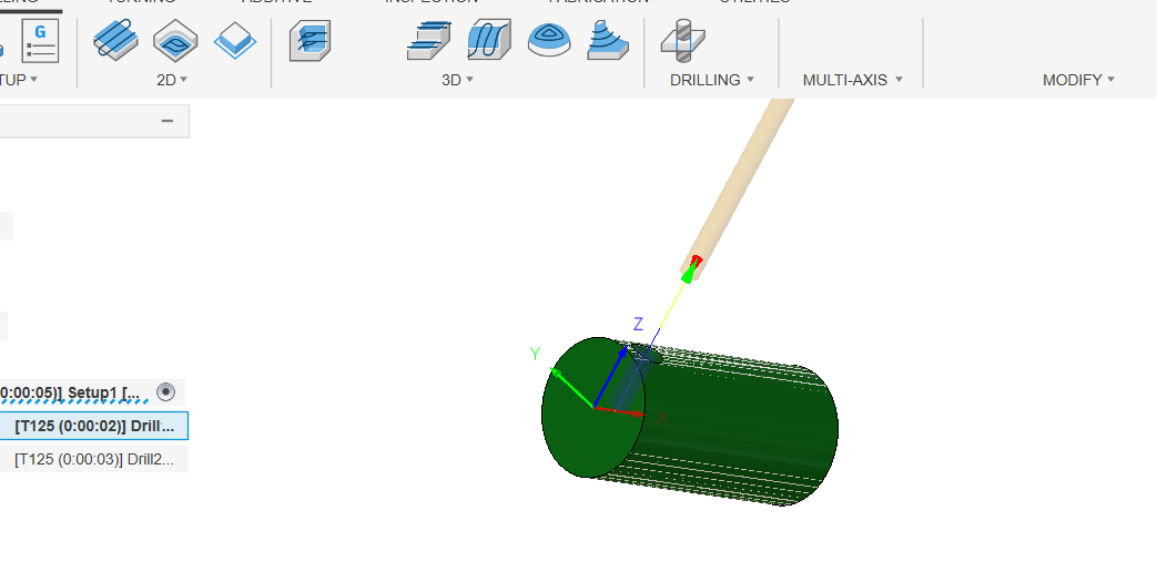
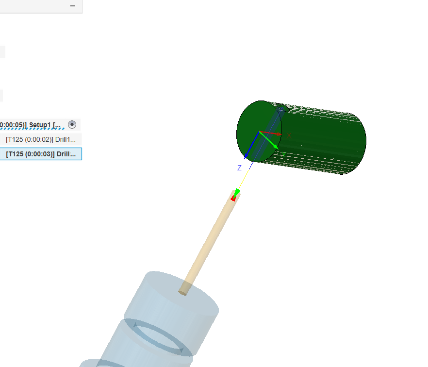
In the design workspace I made a cylinder and put a hole through it (using the cylinder and hole tools, no sketch needed), moved to manufacture and new setup. Set the stock WCS to the centerline at one end, then added two drill ops using a random drill in my library– the first drill op was at the original WCS, selecting the top of the hole, then the second drill op used the tool orientation option to only tick the ‘flip Z’ button. Selected the other end of the hole for the geometry and hit ok with all the other stuff just defaults (no machine selected in the setup). Posted it with Tormach PP Post (#44024 although I don’t think that matters much) and got the A0 moves. Maybe try copying that just in case there’s something in your geometry that is annoying Fusion. Should only take a few minutes.
I don’t have any of the 4th options even visible anymore.
When you post out the operation for the second drilling op just search the NC file for an A180. That will tell you if it’s moving to the other side or not. If A180 isn’t there search for A0, if it’s A0 then the setup in fusion isn’t correct.
One other issue is that I believe my WCS is not set up correctly. I was on the Fusion Cam Facebook group, and David Loomis (from Xoomspeed I am assuming) pointed out to another user that the WCS needs to be in the center of the workpiece for 4th axis operations.
Also, I noticed that the Xoomspeed post-processor inserts a Z#5183. I have read some about this, but don’t fully understand it. It seems that the Z#5183 command is a way to make the z-axis move to “home” position in this instance. But, is the Z#5183 defined from the previous operation? I notice it says “Retracting new work plane - g30z”, I am not sure what that means exactly. If my WCS is in the middle of the part, will it “retract” to the middle of the part (ie. crash)? I guess I can load the program on the Tormach and do an “air cut” to see where it ends up.
Thank you everyone for your help. As with most things, learning the basics of whatever you are doing and developing that baseline understanding is the key to success.
I’m sure that I will still have a “few” more questions.
This is true for any simultaneous 4th toolpaths, but not for indexed 4th operations.
Parameter #5183 is the value of the G30 position for the Z axis. “G30 Z#5183” is equivalent to having the “G30 move in Z only” checkbox on the Settings page checked so I’m not sure of the usefulness of calling it out that way.