I see the drawing on the tormach website that shows the bolt pattern for the za6 flange. I am wondering if there is a drawing somewhere that shows the angle between the zero position and the hole pattern on the flange.
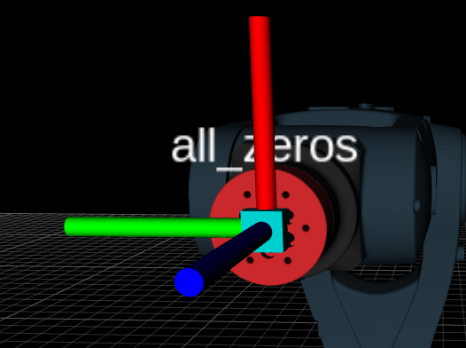
The zero position is marked with a sticker, but the mark indicating zero on the sticker does not match the centerline for either the bolts or the mounting holes.
I can of course empirically deduce an approximate angle, but I was wondering if there were something already available that may be more accurate than what I have found
@John_Morris Gotcha! Thanks for the quick response.
Are the joint limits for joint 6 just artificial then? I had presumed that joint 6 only had two full revolutions in its mechanism somehow as stated on the specs page referenced above and due to the path pilot UI, but I did find it strange that it would be so since there were no wires or anything on the flange.
If it was the case that joint 6 was in fact mechanically a continuously revolute joint, then I would guess that I could just remaster it at a more appropriate position.
We added the joint limits because our actuators come with pneumatic tubing that’s only so long.
You’re right, if you don’t have wires or tubes, it’s a continuously revolute joint, and there’s no reason for the limits. We haven’t added any way to disable the limits. Hindsight…