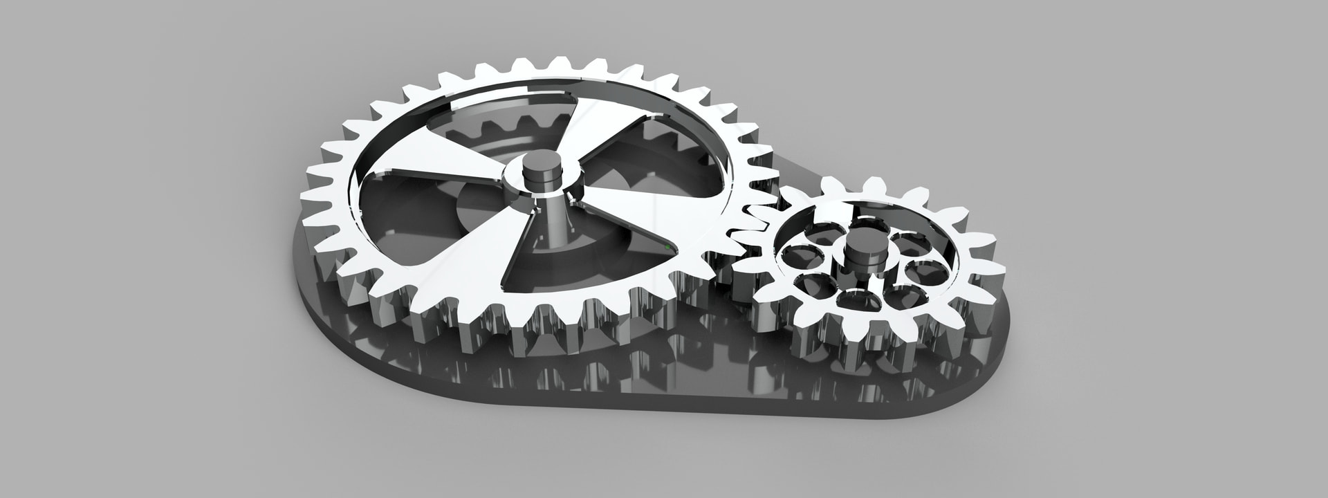
I am starting to work on a project with gears. I have been thinking about the best way to hold them. For the first side, I was thinking about using the cyanoacrylate glue approach. But I am not sure how to do the second side. Any thoughts?
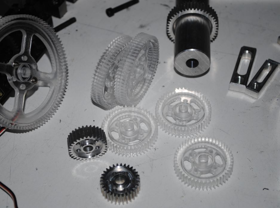
This image is not exactly what I will be machining, but something in this realm:
Mount the stock to the pallet with 8-32 screws using a couple of holes or other interior features. Mill all the exterior features including teeth if you can or want or if that kind of gear.
Then I install in a mandrel and mount in 4th axis and cut exterior gear teeth using a gear cutter mounted in a arbor saw tool holder.
Lane’s approach is exactly what I would do. Raw stock in a vise, cut all interior features. Flip and secure using one or more screws or a pallet cut to the negative form of the interior of the gear, then a screw through the center bore. Depending on the tooth profile, mill those in the second op as well, or add a third op in a 4th axis or indexer to cut the teeth with a gear cutter.
If you want to do one (or more than one) all in the vise, you can also cut the gear into some stock that’s too thick sitting up high so you can get to all the sides, then flip it over into some soft jaws with a circular bore for the gear OD and face off the back. It wastes some material but all the key features are done in the same setup.
Quick question, with the first scenario where you machine the interior features, then flip over and use screws to hold the part in a pallet cut to the negative form of the interior, I follow the process, but don’t understand how the screws holding the part to the pallet don’t get in the way of machining the second operation?
The second approach using soft jaws is also interesting. I wondering if for smaller gears with lots of teeth, you can make soft jaws that press on the outside diameter of the teeth (as if it were just a cylinder) and machine side two? I am assuming you would machine something into the jaws to register the gear position. Does this sound workable? I will be machining 6061.
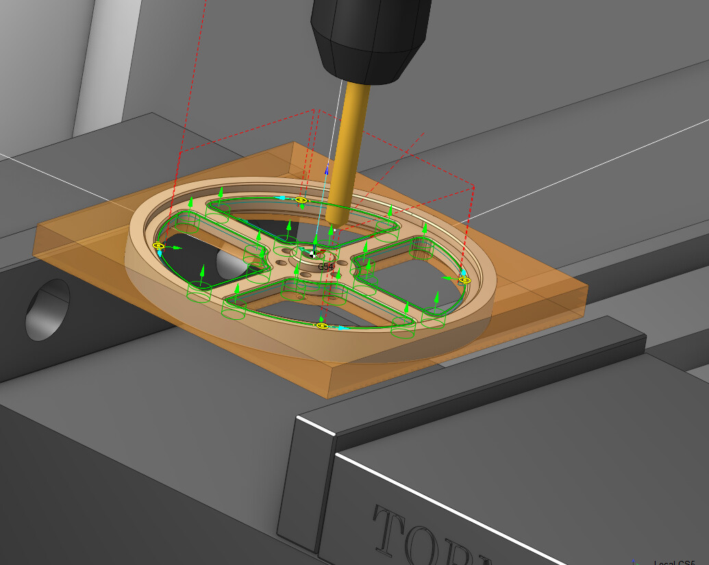
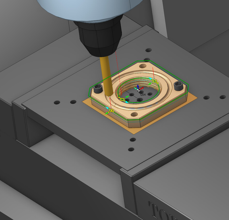
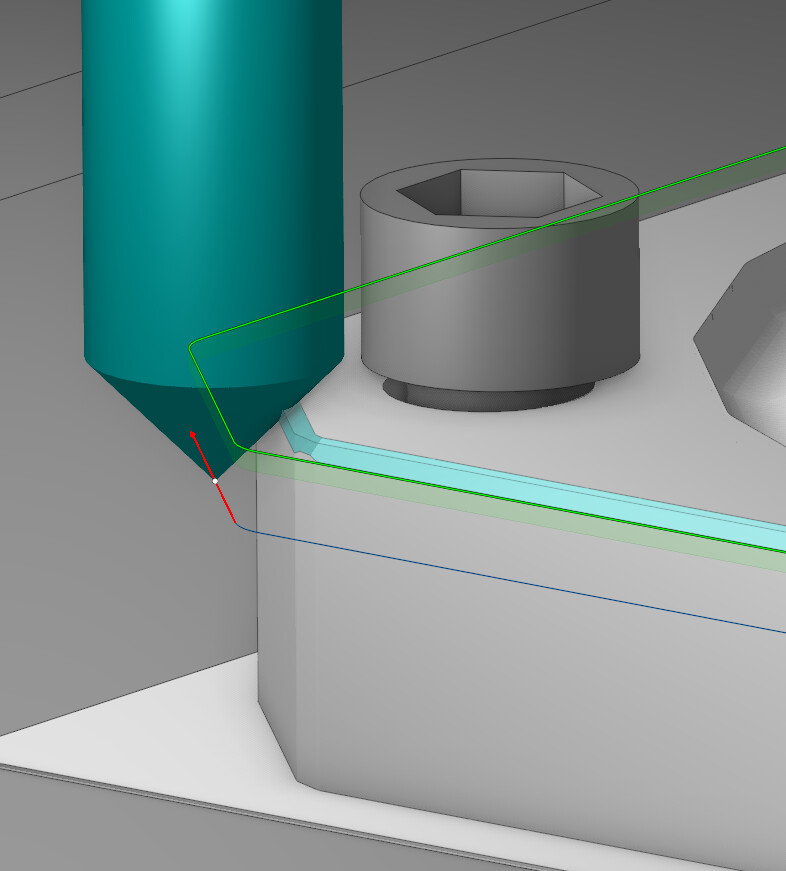
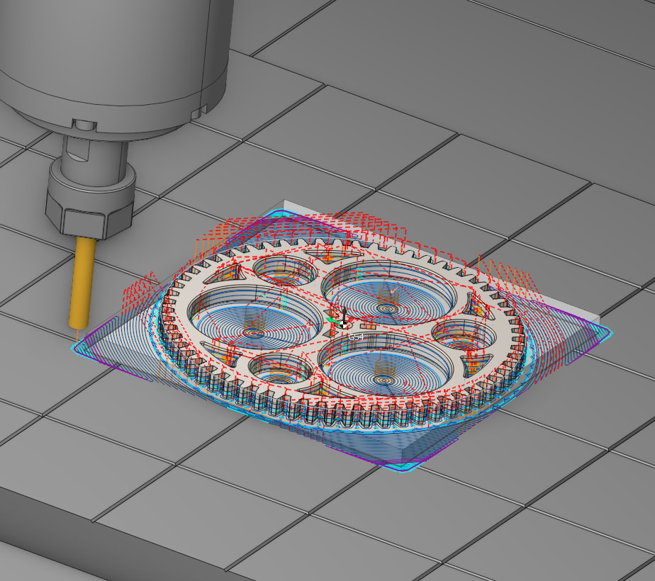
I included the screws in the fixture setup in my cam program setups. I use collision detection to see if I am hitting a fixture, plate, screw or clamp. With experience the extra time spent including all fixtures in cam setups will save on drama and broken tools . Shown below
A cylinder bore will do fine with aluminum IME with aluminum soft jaws. Make the bore close to full-depth on the gear. You don’t need to index it if you are just cleaning off the extra stock for a flat gear, but if you do want to do something cosmetic that matches up to the other side (chamfering the teeth or spokes, etc), you can put an index pin in somewhere convenient or machine the jaws with matching teeth.
For a one-off however, I’d probably use a fixture plate over making soft jaws, even if that fixture plate was just a bit of flat bar with a few holes drilled to bolt the first op down.
Lane, thanks for the clarification. That makes lots of sense and I will certainly be using this approach shortly. I have identified things like soft jaws as fixtures in Fusion before but never thought of including screws. Funny, I was just looking for a video on YouTube to explain how to use the machine library and use machine simulation to create better simulations. This is definitely something I want to learn how to do. Thanks for your thoughts.
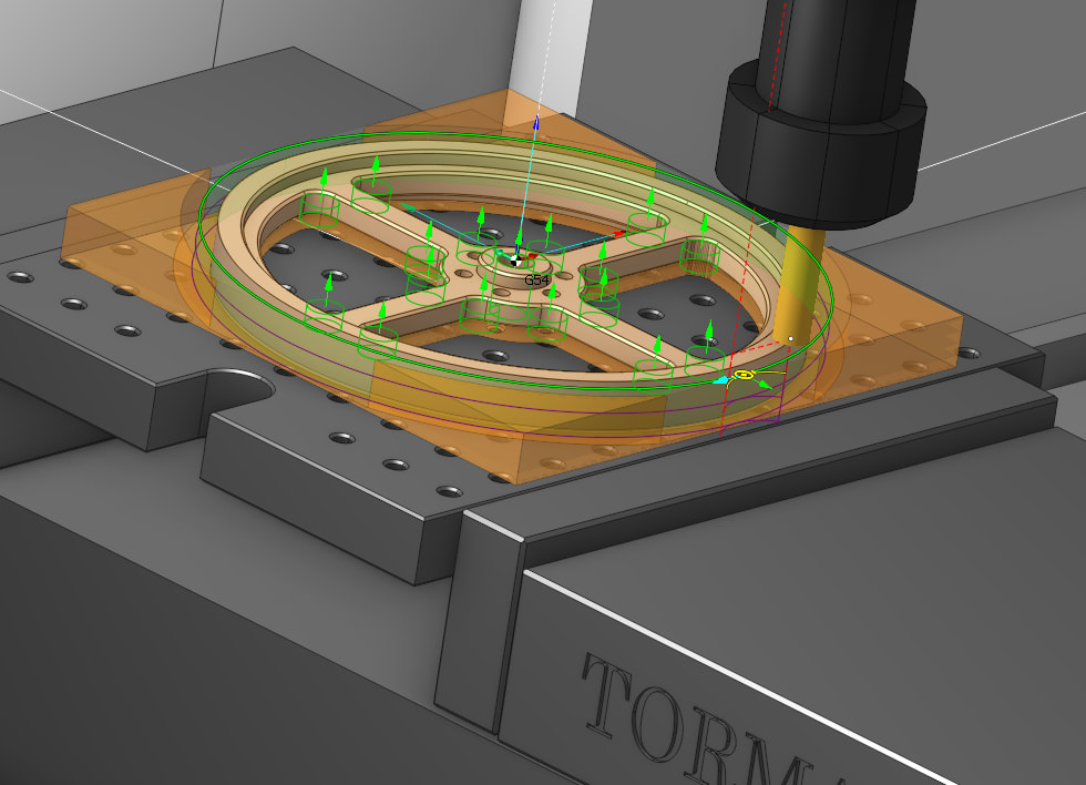
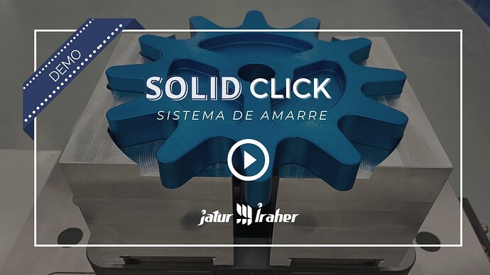
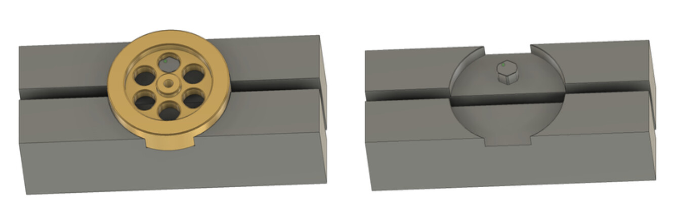
Roy, I’ve made a bunch of soft jaws in the past but did not think of them for these gears. Below is an image of one I did for a flywheel that I think would work well for these gears.
Thanks again for all these ideas. Really appreciate it!!!
For one off stuff, 3D printed softjaws can be awesome. I’ve used them a few times myself. Just have to be careful about clamping forces so you don’t distort the plastic too much.
I am a chief engineer at The Gleason Works, and work on designing the machine tools that are use to make gears. The one thing I would add to the suggestions above is that to achieve good performance, do your best to cut the teeth with the workpiece being held by the same datum surfaces it will be operated on - On a part with an internal bore, use an expanding mandrel on that bore in it’s finished form. On a shaft gear, hold it by the bearing surfaces. Run out and the effects of position error can have a bigger effect than you might think, so “aim small, miss small”. Best of luck!
“ to achieve good performance, do your best to cut the teeth with the workpiece being held by the same datum surfaces it will be operated on - On a part with an internal bore, use an expanding mandrel on that bore in it’s finished form. On a shaft gear, hold it by the bearing surfaces. Run out and the effects of position error can have a bigger effect than you might think, so “aim small, miss small”. Best of luck”
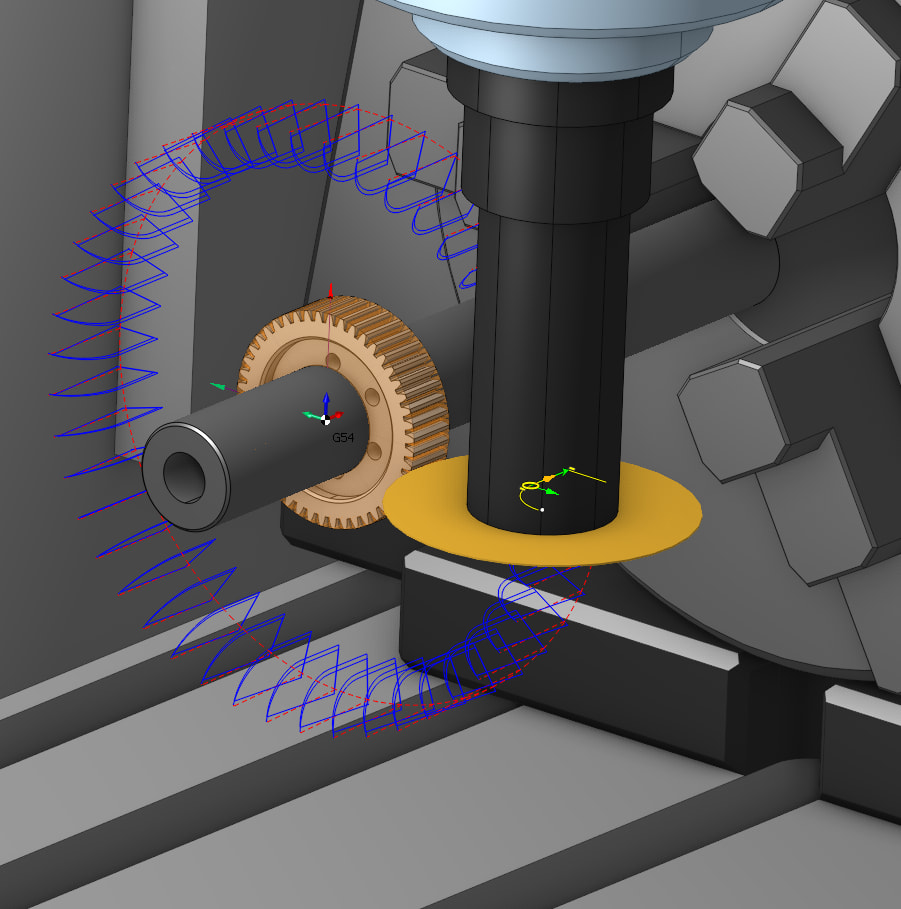
Most of the time I keep this in mind and use a lathe to create exact center and diameter “very important”. Then clamp in mandrel or expanding arbor and cut teeth on 4th axis on mill.
Then if there interior features to be added like holes or spokes I will clamp to a plate and cnc those features on both sides using the center as datum. At this point the gear center and diameter precision is established and all the interior features are cosmetic so if they are off a tiny fraction its no big deal.
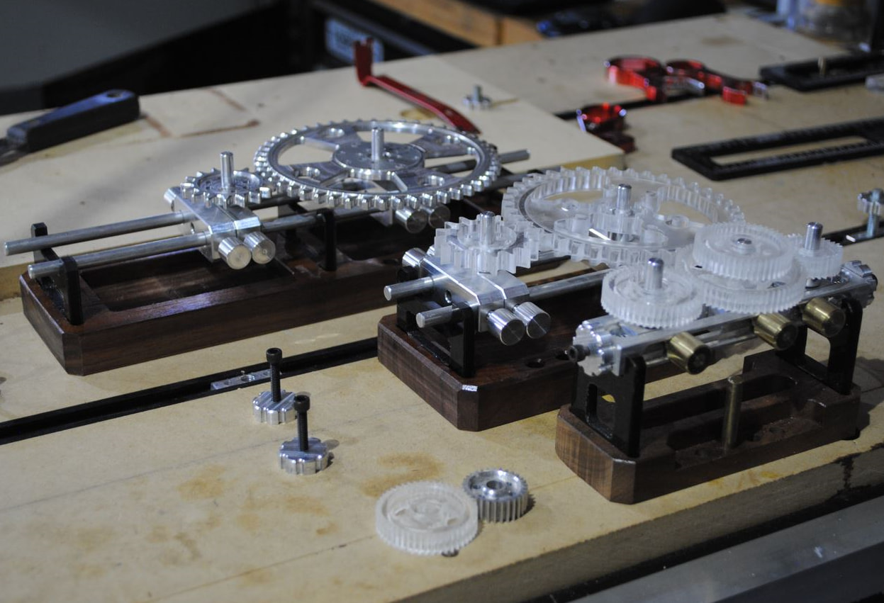
I also made a few different sized gear depthing tools “pictured below unfinished” to establish correct on Shaft center measurement verse theoretical. These are handy to fine tune shaft spacing and can be made in different sizes and styles.
As noted above I try to create diameters and centers on a lathe then cut teeth on mill 4th axis
Some gears are to big like the clock gear show below.
I use router or mill depending on material and use any number of work holding methods depending on their design. I have done these in sheets where there is a half dozen different clock gears all cut on router at one time.
I did one project with 3D printed soft jaws and it worked great. The next project slipped out of the jaws. What are you using for material and how much torque are you using to close the jaws?
Lane, thanks for your thoughts! Funny, I have been searching for some nice looking gears. I like that one you showed with circular cut-outs. The project I am working on is a kinetic sculpture of sorts consisting of a number of cool looking gears.