Hi Richard, I used PLA+ but can’t objectively say how much pressure I put on. My use has mainly been for flipping over the job and holding it while decking off the bottom residual material. I either use the SuperFly or SheerHog for this and keep the DOC fairly light (my work material is either aluminium or brass). Not much help I’m afraid but I use this fairly frequently with 100% success rate so far…
When I started playing with 3D printed jaws, I printed a few sets to test to destruction which was a useful experience. For me the fiber-filaments (CF or GF) seemed a bit more grippy and maximizing clamping area and picking direction of the layers was important.
Thanks. Funny, I was thinking about testing some carbon fiber Petg.
Just curious, I am new to using flood coolant. I was making a part that will collapse if you use too much torque on the vise (standard soft jaws) . Do you typically have to clean off the jaws with something like alcohol to make sure there is no remaining flood coolant from the previous operation so the coolant doesn’t make things slip?
Richard
I wipe or blow off excess coolant but not wipe it down as I figure coolant is going to get in there anyway and I’d rather not be that close to the edge on grip margin. Heat is the enemy for 3DP parts so you need coolant or to cut very slowly.
I do a lot with PETG and it works well, but it can be slippery and does deform under load as you’d expect. PLA is a little more rigid in that regard. The nylons aren’t as rigid but seem to be stronger overall.
For weak parts you might consider printing a sacrificial reinforcing insert to take some of the load or bolting it down from the top if that works. I do that often for thin and bendy parts.
Thanks… That is very helpful.
@Roy @Richard_Salzman since you have thrown some knowledge nuggets our way in this thread, is there any sort of authoritative FAQ/knowledge/guide on 3D printing soft jaws that you can point folks to or have you come by this knowledge from the school of broken carbide and scrapped parts? ![]()
Markforged has some whitepapers about using their CF-Nylon and long-strand fiber reinforcement for jaws, jigs and fixtures that might be worth a look.
I use Delrin or hdpe always keep some around. It’s easier to just mill it as you already have the design and printing takes all day.
Guys, thanks for the work holding tips. Since I am not chamfering features on the rear of the gear that require registration, I chose to machine these gears with soft jaws. This worked great… Thanks for the suggestion!!
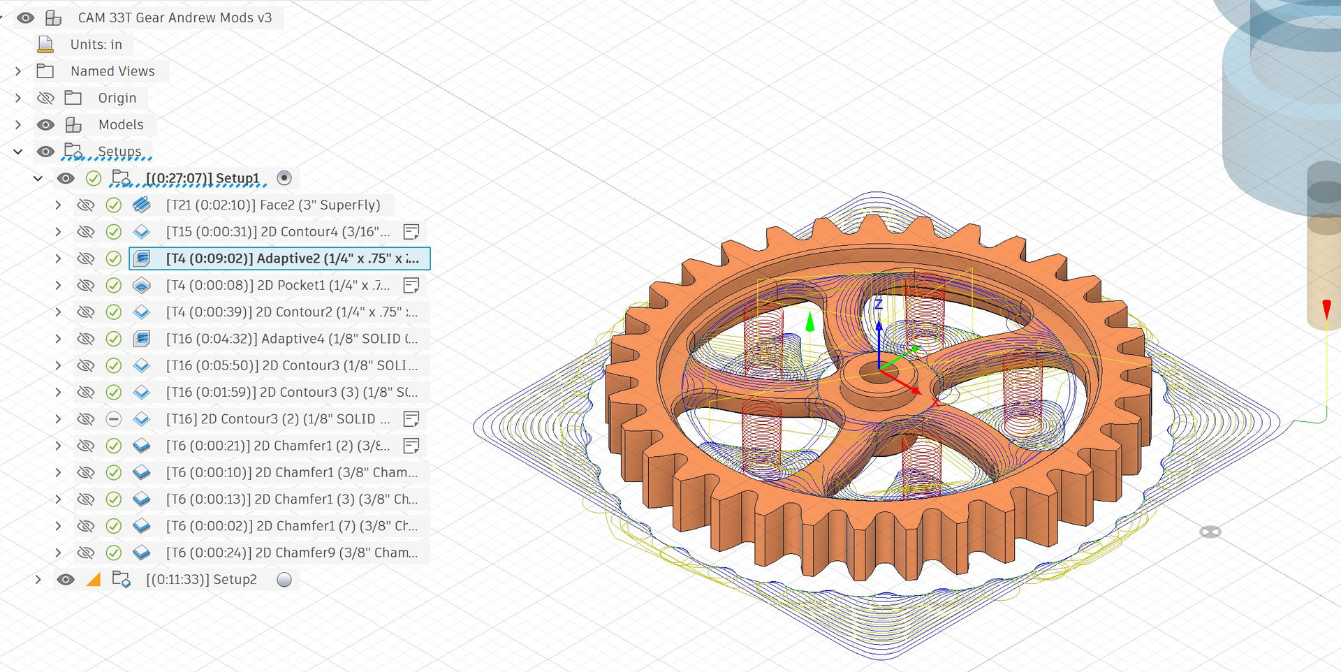
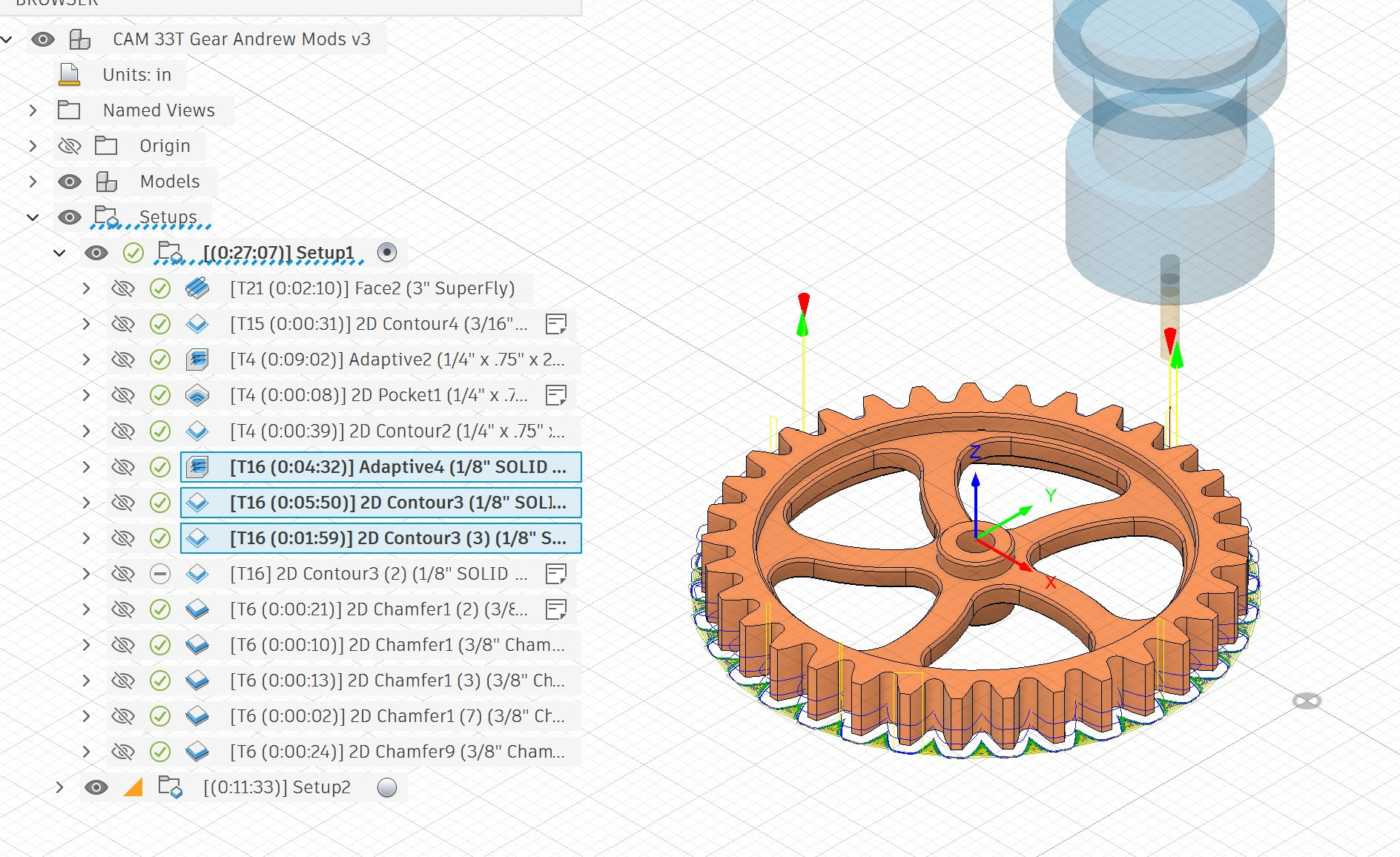
I did however run into a feeds and speeds challenge. The root filet radius for these gears is .07, only slightly larger than the 1/8” end mill I’m using to machine the tooth profile. A senior machinist on the Fusion CAM forum helped me a bit with the F&S for this run. In short, the approach was to use a 1/4” YG1 aluminum specific end mill for with 3D adaptive and a few 2D contour tool paths to rough out the part and finish the interior (see below), followed by a 2D Adaptive and a couple contour tool path with a 1/8-inch aluminum specific end mill.
The 1/4” end mill worked fantastic. I ran 10,000 rpm, 130 ipm, .4 DOC and .033 optimal load. Even during the 3D adaptive, the surface finish was an absolute mirror.
The 1/8” end mill was not so successful. The suggested F&S for the 2D adaptive was
10,000 rpm, 22 ipm, .4” DOC and .013 optimal load. This results in a chip load of .00045 adjusted for chip thinning. Keep in mind that this was the first time I ever ran a small end mill and still getting use to the 1500mx. With five nozzles blasting the work piece with food coolant it makes it harder to see what is happening. I learned quickly that a subtle ringing sound is the sound of chatter… and at these feeds and speeds, I got plenty of chatter. The suggested finishing speeds were similar with smaller WOC and I still got chatter. I tried making adjustments but could not make anything work at 10,000 rpm. This surprised me because the spec sheet for this endmill indicates higher rpm (see link below).
I adjusted the F&S as follows for the 1/8 inch end mill:
Adaptive: 8200 rpm, 44 ipm, .21 DOC and .013 optimal load. This resulted in a chip load of .00109 adjusted for chip thinning. Finishing: 5000 rpm, 15 imp., .21 DOC and .004 WOC.
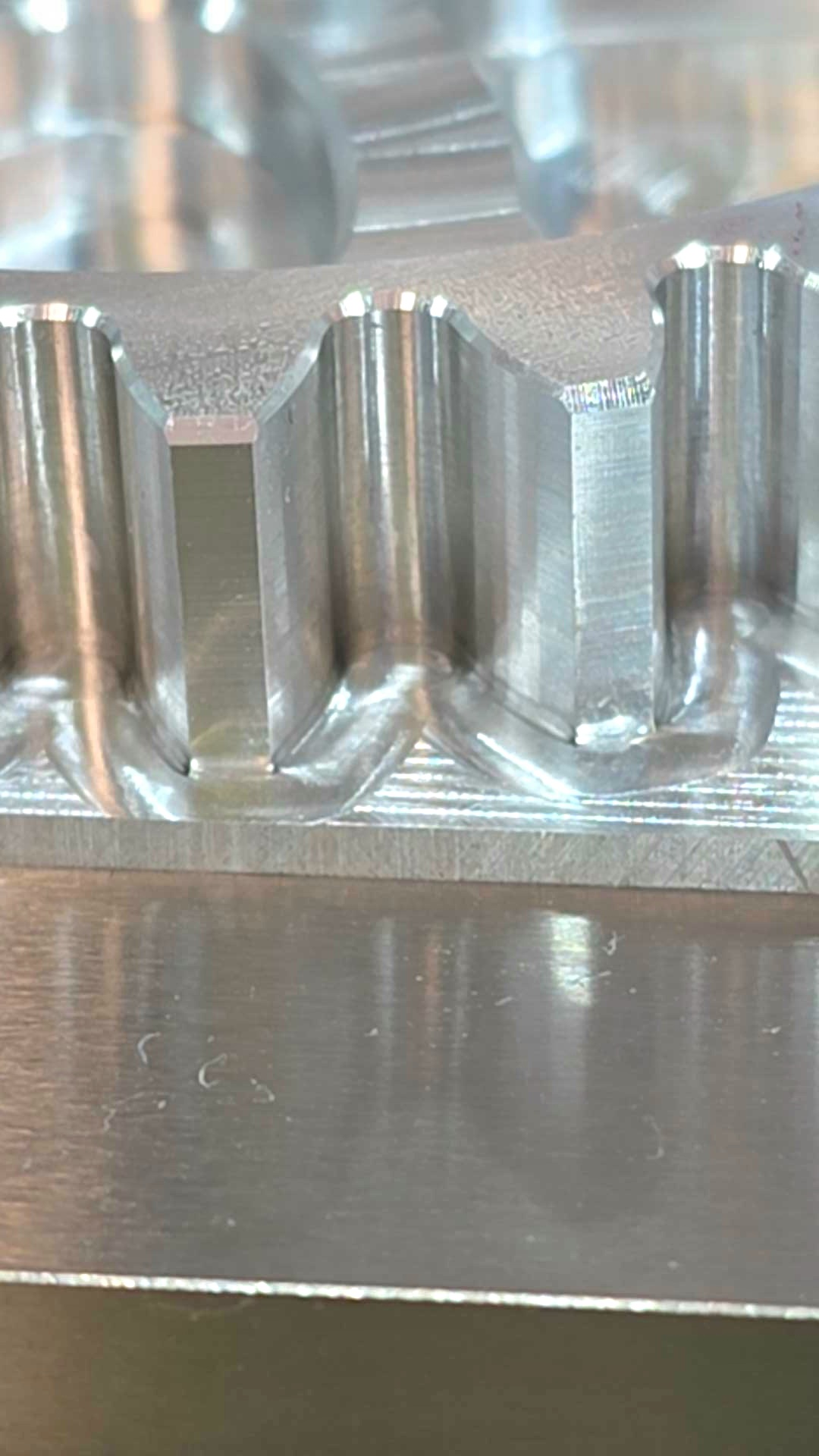
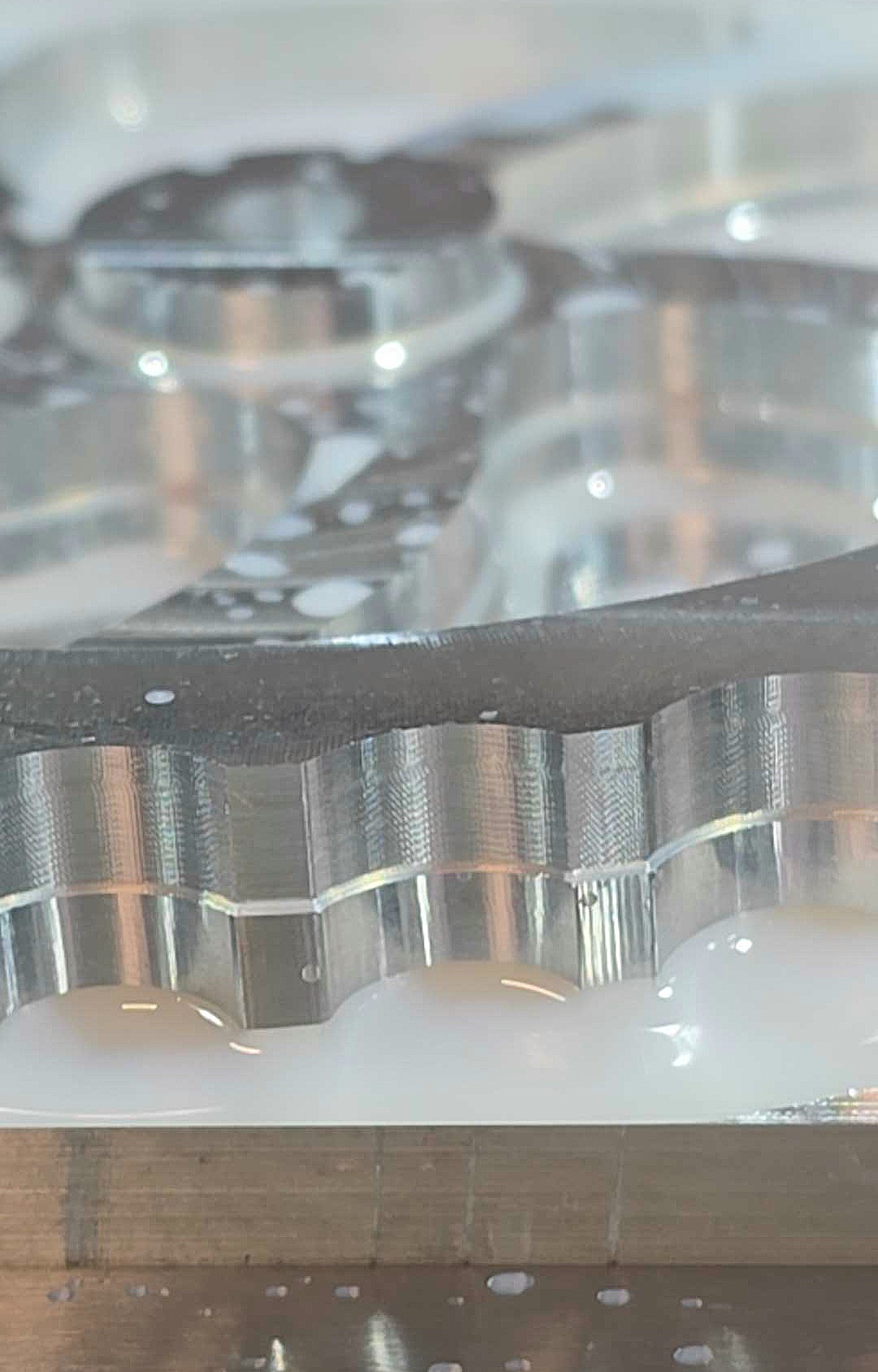
With these F&S and reduced DOC, I got what I feel are decent results with room for improvement. The close up below shows the surface finish.
My beginners’ guess here is that there is some harmonic going on here that at 10,000 rpm is resulting in chatter. I have several more gears to run and my gut feeling is that if I increase the chip load and optimal load a bit, I think I can get the speeds up to 10,000 rpm without chatter.
Someone else on the Fusion Forum suggested an optimal load of .03 which looked heavy to me. What are your thoughts on this one? Also, looking carefully at the flank of the tooth, I see some straight sections making up the curve. How can I avoid these?
Thanks…. Richard
1/4 Inch End Mill:
1/8” End Mill:
GWSCUSTOM350 Speeds & Feeds.pdf (1.4 MB)
1 Like
Hard to see from the drawing but it looks like the little endmill runs into a sharp corner at the root of each tooth and that is going to cause squawking,
Thanks Roy. The root filet radius is .07”, the end mill’s radius is .0625. I don’t believe I had any squeaking or chatter at the slower speeds.
The “tap test” is what I don’t think anyone on here has the equipment to do but might answer this question. If it is harmonics, then adjusting RPMS and feed parameters is your path. Maybe not exactly 10k but something less where it doesn’t hit the offending harmonic?
If it is squealing right when it goes into a sharp corner, you might look at the feed optimization tab to see if that can help (drop the feed rate for that but keep it up for the rest)?
I did use some feed optimization. Here is the file if it helps:
Best… Richard
FWIW, I am not a machinist by vocation or formal training, but applying my decades of diagnosing general problems across many domains…
In the file uploaded, feed optimization is not turned on for T16 Adaptive4 1/8”. Smoothing is. Default parameters but dropping the feed rate shows there is a set of parameters that would result in slowing it down at some point in the tool path (it overall, takes a bit longer when turned on).
Not 100% clear from original post if chatter noise is present during the entire cut (that’s what I take away, that it is no bueno the whole cut and why you adjusted RPMS down and other parameters, despite the tool calling for higher) or if it is just in the last part of each recess where the EM machines the most innermost part of the tool path between teeth (where you might be able to keep your parameters but potentially have it slow down for that part of the tool path based upon the characteristics of that particular part of the path).
Since you don’t have much experience with 1/8” on this machine, have you considered loading some scrap stock to determine if the cut parameters are okay steady state on a simpler tool path (e.g. spiral outside to inside at a steady WOC/DOC/RPM/Feed and evaluate, adjust, evaluate) to isolate overall cut?
Otherwise, if it is just the part of the cut in the adaptive strategy where it goes into the crevice of the gear and loading up when it goes in the corner as Roy postulates, then I would think that my CAM suggestion might be the way to fix that one issue.
Thanks for your thoughts. Initially there was chatter throughout, then just in the tight corner. I dropped the rpm to see if it would solve the problem, which it did. I don’t know why the folks on Fusion CAM said now to use feed optimization on the adaptive tool paths. I am going to turn it on and experiment today a bit. I will keep you posted.
Thanks for your thoughts.
Richard
I would change the program to do a finishing pass of .0008 t full depth If that doesn’t smooth it out you might make a path that traces the gear tooth arc profile with a loop in the galley. It’s a bung more work in the path but it should clean it up.
I spent lots of time with this today and could not get a good finish with this until I swapped end mill to a YG1 end mill. Then, any of the S&F worked fine. The original end mill is a high quality GWS aluminum specific end mill as well.
The YG1 end mill has a LOC of .375”. The GWS is .5” Can I machine the depth of .4” with an end mill that has a .375” LOC?
I have attached the mfg sheets below.
Thanks… Richard
00 YG1 Feeds & Speeds YG1E5981.pdf (172.5 KB)
GWSCUSTOM350 Speeds & Feeds.pdf (1.4 MB)
I am stumped with what is actually happening I swapped the original GWS aluminum specific end mill for a similar YG1 aluminum specific end mill. Immediately, all was good. I tried the suggested feeds and speeds from Andrew as well as those suggested from Programming2C78B (from the Fusion CAM forum) and both worked perfectly well. I even re-installed the GWS end mill in a new collet thinking that might be the issue but continued to get chatter.
This makes no sense to me. The primary difference between the end mills is that the GWS has a .5" LOC and a Zrn coating while the YG1 has a .375" LOC and bright finish. I am really at a loss here as I have no idea why these end mills are acting so differently. Looking at the spec sheets (see below), the GWS end mill has higher speeds which I believe are due to the coating. The funny thing is that these end mills even sound different. With the YG1 all I hear is the sound of the spindle, I can’t hear any noise. The GWS makes a slight sound when it is cutting.
Let me know if you have any idea… Richard
The top portion of the image is an amplified view of the chatter from the GWS end mill:
Uncoated lapped carbide is the best choice for aluminum finishing.
You should be able to cut the rest of the depth with the yg, just make the full depth cut very light.
If you look at this Page for the metric version (as close as I could find the profile specs are (1.5D step down) (.15D stepover) its metric but you should be able to find the inch equivalent pretty easy. Usually you can calculate the ratio for an end mill using the slot and profile settings to plot 2 points on a line and then any point on that line is probably safe.
Thanks for the information Harold. If I machine the part with the Yg1 tool, do I have to be concerned with the shaft of the end mill rubbing?