Would it be possible to get updated STEP files for the ZA6 (preferably models that are not tesselated)? The models provided on the wiki page and the za_description package on the controller seem to have an old version of link 5 and the flange. I am also wondering if this affects the link offsets in the URDF files, since the fifth link and flange on the physical robot are longer than the ones provided in these models.
The models on the wiki page are dumbed down and (unfortunately) slightly out of date. The URDF should have the correct link lengths and offsets, so J5 should be OK, but we will double check to be sure - thanks for asking.
I’ll ask one of our engineers to use the current manufacturing solid models to create STEP files for the current version of the ZA6. It might take a little while (they need the internals removed/defeatured) but I will post them on the wiki when they are done.
@Rogge - Thanks for having me, excited to be here!
It’s great to hear the models are being updated - I will be on the lookout for those.
In reference to the URDF offsets, (in the files that I have) the flange frame is 100mm away from the axis of rotation for joint 5. In reality, I measure this flange offset to be 117.5mm with the new flange geometry (it would be great to get a confirmation on this number). If this is the case, then all forward and inverse kinematics of the arm are currently not working correctly (hopefully I’m wrong).
Of course, If the user is just setting joint positions of the robot or you have applied the 17.5 mm’s to your tool offsets then there should be no issue.
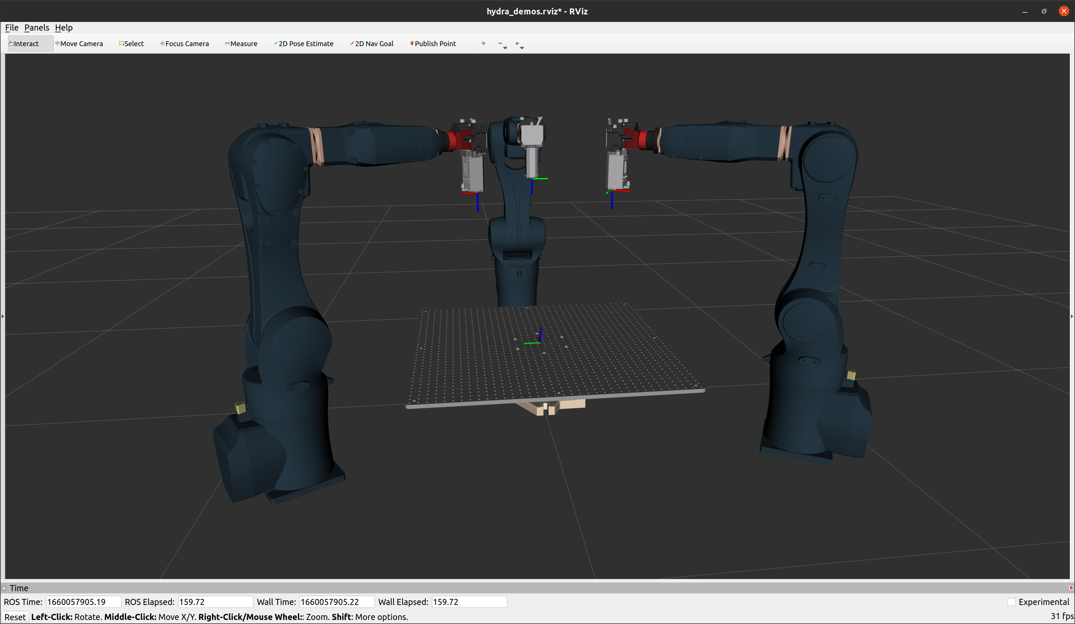
As for my application, I am developing a multi-robot wire-arc/polymer 3D printer (pictured below) as part of my PhD work. I am using the CAD files in my system designs to test the reach of each robot with respect to a positioner table as well as designing peripheral equipment for each robot.
In the meantime, I have developed my own versions of the robot’s URDF and some additional MoveIt kinematics plugins that I would be happy to share with anyone in the Tormach community that’s interested in the ROS side of things. These can be found at the following links
STL files converted to Collada files to prevent the transparency issues with robot links
Updated flange to match physical robot
Offset link geometry origins so there is only a single offset between each joint (this helps the ikfast kinematics generator to develop better solutions)
I have measured this plugin to be approximately 25x faster (per IK call) than the ikfast plugin that came default with the za6. This is a result of changing the urdf file to have a single offset between each joint. I am not sure why this works, but I would be happy to elaborate on this process if you are interested.
Thank you for taking a look at this. There were some later changes in the robot flange, which could be the source of the difference. So yes, I fear the kinematics might be slightly off. Luckily, this only happening in J6, so the difference should be minimal. We are definitely going to fix the problem
Regarding the description and ikfast plugin:
I’ve noticed you have removed the 1mm offset at J3 and J5, unfortunately this is not an error in our URDF but an actual physical property of the robot, which unfortunately cannot be easily combined due to the rotational J4 axis in between. We have noticed that this breaks ikfast, by making it relatively slow compared to typical 6-DOF robot arms without this offset, and actually consistently faulting in some configurations. Therefore, we are not using ikfast in our application, but instead we use bio_ik, which leads to significantly better results with this particular robot arm.
However, I’m happy to take a look at the geometry origin changes when updating the robot models to see if this would produce a working ikfast plugin, even when re-introducing the 1mm offset.
I’ll also take a look at the Collada format or maybe at fixing the normal of the STL, but I can’t promise this actually fixes the translucency issues in our Robot UI.
You are correct, I guess it slipped my mind that these 1mm offsets cannot be combined. It is so unfortunate that these are part of the physical robot as they cause a multitude of errors with IK solvers that work for almost all other industrial robots. It looks like the geometry of the za6 is pretty identical to the KUKA Agilus (kr6 r900), yet that robot does not have these 1mm offsets.
For my application, bio_ik runs around 10 times slower so I am afraid I must stick with KDL. I tried recreating the ik_fast plugin with the 1mm offsets, the result was around 20 times slower than without the offsets. I guess ik_fast just works better with spherical wrists, and unfortunately, this wrist is not spherical with the 1mm offsets.
I might try my hand at deriving the analytical IK solutions, but this might be a nightmare. I will post here if I make any progress.
These solver times will likely not be an issue for many others, but I’m trying to plan hundreds of thousands of positions so a 10 times IK solving time increase takes my planner from around 1 minute to 10 minutes on average.
I’m not 100% sure how the visualization in path pilot works, but if you’re using an rviz plugin (or at least a method related to the way rviz renders models) then I believe this should fix the transparency issues.
I had originally specified the inertial information for the Za6 in my za_description package. I recently removed the inertial tags from my xacro/urdf since I mainly use kinematic simulations (i.e. Rviz instead of Gazebo).
The values I used for the center of mass and the inertia matrix were very rough estimates. I divided the total mass proportionally across each link based on the volume of the solid model (found here), and the CoM was found in SolidWorks. So, take the inertia values with a grain of salt.