Probing Routines on ZA6 - Creating Work Offset for VersaBuilt Vise

I’m hoping to create a somewhat automated way to probe my Versabuilt vise to create a work offset for it in order to ease training the position of the vise jaws. There’s quite a few moving parts in this idea, so I wanted to validate it a bit and get feedback on this approach before diving in.

Mechanical:
First of all, mechanically, the VersaBuilt gripper has a couple of unused tapped mounting holes that I think I will 3D print a bracket for to hang a standard 0.75" shank probe from, TTS-or-compatible. I’ll post the models of that when I get it dialled in. This should allow the probe tip to hang just below the gripper and stay basically permanently mounted, and more importantly, allow me to create a fixed tool offset for the probe tip so that I can set that for the subsequent operations.

Probing Sequence

With the probe mounted, I am imagining instructing the user to jog the probe tip over the bottom right corner of the vise, then I think there are two discrete probing sequences that occur (unless there’s a better way to do this).

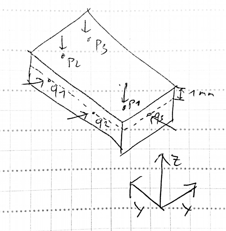
  1. Vise X,Y - Probe bottom right corner, and then use vise dimensions as a cue to probe two other points to determine X/Y vectors of vise.

  2. Vise Z - Once position of vise is known, probe 3 points on Z to establish Z plane of vise.

I am imagining using the basic probing function for grabbing these points.

contact_pose = probel(probe_goal_pose, a=0.5, v=0.01, v_retract=0.1, away=False)

Work Offset Calculation

This is the part I am slightly unclear on, although maybe it will become more apparent as I dive into it.

I believe, based on my probing, I should have the data required to input to:

robot_command.calibration.calculate_work_offset_4(origin_wp, x_axis_wp, y_axis_wp, position_wp) -> robot_command.rpl.Pose

The only thing here, is that I’m a little worried about how to compute position_wp. I am imagining in an ideal world, this would be basically the XYZ of say the bottom right of the vise, but based on my probing, I am going to have XY, but Z likely offset downward by 3mm or something for the probe tip. I think it will be close enough to just change to the Z of origin_wp if I sample them close together - but open to feedback on that one if there’s a better way to define the work offset.

In an ideal world, what I’d like to end up with is a work offset where the origin is the bottom right corner of the vise, and the plane matches the Z surface of the vise.

Does this sound like a reasonable approach, or am I over-complicating things?

Hey BigTChopShop! Welcome to the Tormach user forums.

There are a number of ways to solve the problem you’ve identified and your approach strikes me as viable. Perhaps you have already thought of this, but I would create a tool frame for the probe that is separate from the tool frame for the FJ gripper. I’d try to be as precise as possible when creating this tool frame. I’ve got a couple of quick tip videos on tool frames here:

If you have accurate CAD models for the proe you use and the 3D printed bracket that match the real life setup, you could compare XYZ translations with the tool frame values you get using the robot tool frame measurement routines to give you a gut-check.

Then I’d approach the probing routine just as you outlined above, but with the probe tool frame active. The returned values should allow you to set the vise XYZ (and maybe a tiny amount of ABC if the robot’s base isn’t planar with the vise’s base) appropriately with the calculate_work_offset_4() command, with no subsequent need to calibrate the multigrip gripper to the probe.

@machinekoder may have different or better advice :slight_smile:

Thanks @Rogge. I am glad to hear that I’m in the right ballpark. The tool offset makes total sense. That’s actually one of the things I realized about this process and the tending problem in general. I think there’s two tool offsets (MultiGrip gripper, MultiGrip “probe”) and then two work offsets (Vise, Picking Area Grid).

My thinking is that once you’ve got that vise work offset established, the positioning of the jaws is sort of an X,Y,Z thing in the coordinate space of the vise work offset, which simplifies matters from a tuning or fine adjustment perspective.

If you happen to lose that work offset for some reason (moving the vise, or changing a setup, making a mistake), the probing routine should be able to pick it up again, and any of your other tuning relative to that work offset should stay the same.

The devil is in the details, but conceptually, I think this idea is coming together.

Just had one other thought / question as far as probes are concerned while watching the video.

If I were to run the tool offset procedure with a probe - I’m assuming I should jog until the probe trips on my reference point to account for the effective diameter of the probe.

One thing I am not super confident in here is whether a probe trips evenly “off axis” so to speak. I am assuming they do, but if we we think of a probe in terms of Z being up/down, and then X/Y, on a mill, you’re never really probing an X/Y+Z offset (at least not intentionally) it’s always X/Y, or Z.

Do you think there’s any concerns with that, or are probe internals such that the amount of deflection needed to break contact on Z is the same as X/Y, so it’s ok to come in at sort of an off-axis X/Y+Z point for probing? The alternative, I think is to make sure I’m touching off with ABC rotations basically at either zero or 90 degrees perpendicular to an axis. But, that’s a little tricky with a probe in this scenario.

That’s a really good point - the tripped position is always offset by the effective diameter of the probe (the probe stylus radius + the travel distance to trip the circuit), and that offset is in the direction of motion. On a mill that’s either X, Y, or Z, but for the robot it’s a combination. Let me think on the best way to calibrate a probe tool frame - I bet we can come up with something better and easier than jogging until the input changes state.

Creating a work offset from 3 points on a plane can be done using calculate_work_offset_3, I would use this for first measuring the top/Z plane of the vise. (p1, p2, p3 in the image)

Using this new work offset, you can then measure two points each on the Y and one on the Y axis of the vise, let’s say 1 mm below the vise top surface. Those 3 points (q1, q2, q3) will be on a 2D plane, which makes it possible to calculate the origin point of a rectangle containing those 3 points. Add 1mm in z to the calculated rectangle origin point and to let’s say q1 and q3 to create a new work offset aligned with the vise top surface, origin in the bottom right corner.

1 Like

Blockquote

If that is correct, if probing a (perfect) plane should always result in the same amount of deflection. This would make it possible to create a work offset and then approach aligned with the Z axis to measure the actual Z tool offset, including the probe trip offset.

Good point. It could be a 2 step thing (which I also see in the post below). Once you’ve established the plane, then you can approach at a known orientation to do an accurate measurement on a known axis.

Smart! Yes. I like this approach a lot. Once you have the plane determined then it’s a fairly straight forward process to grab the corners and set up the origin.