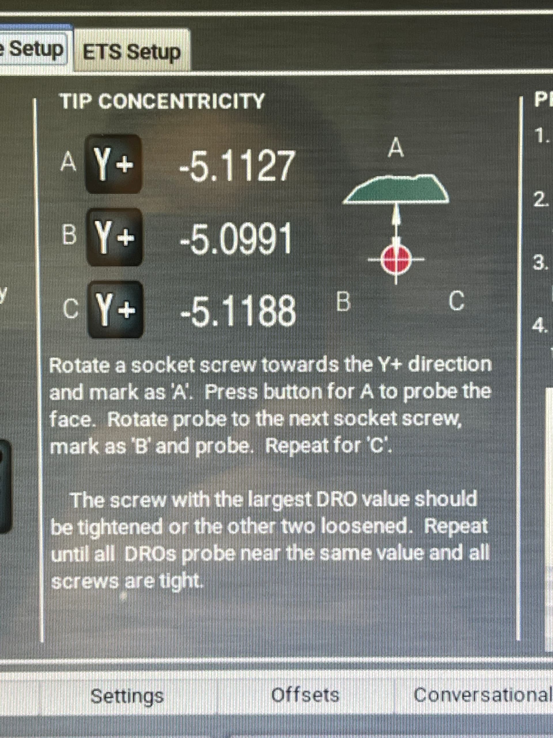
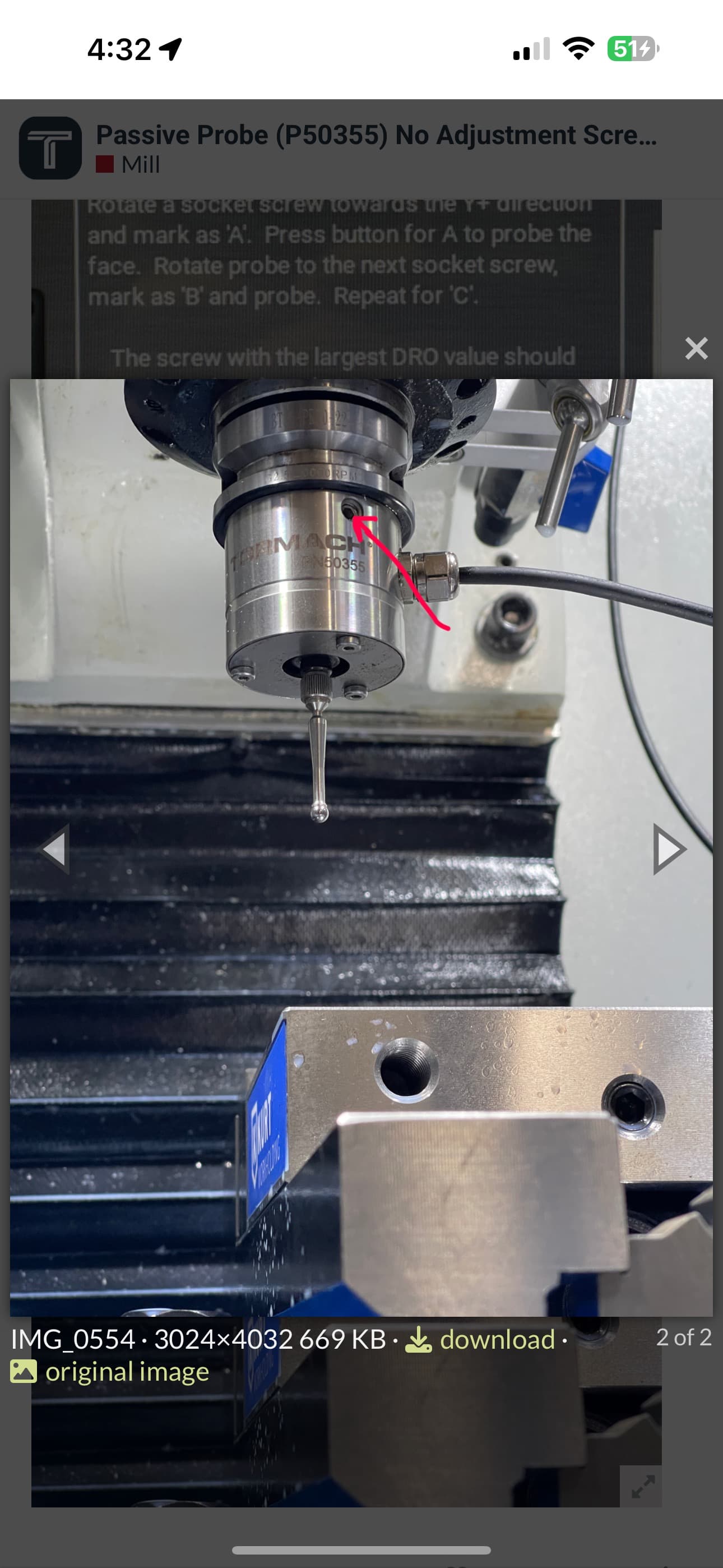
Does anyone know where the adjustment screws are on this probe? The tip concentricity is really quite far out and I am at a loss of how to adjust the probe since the usual adjustment screws are missing.
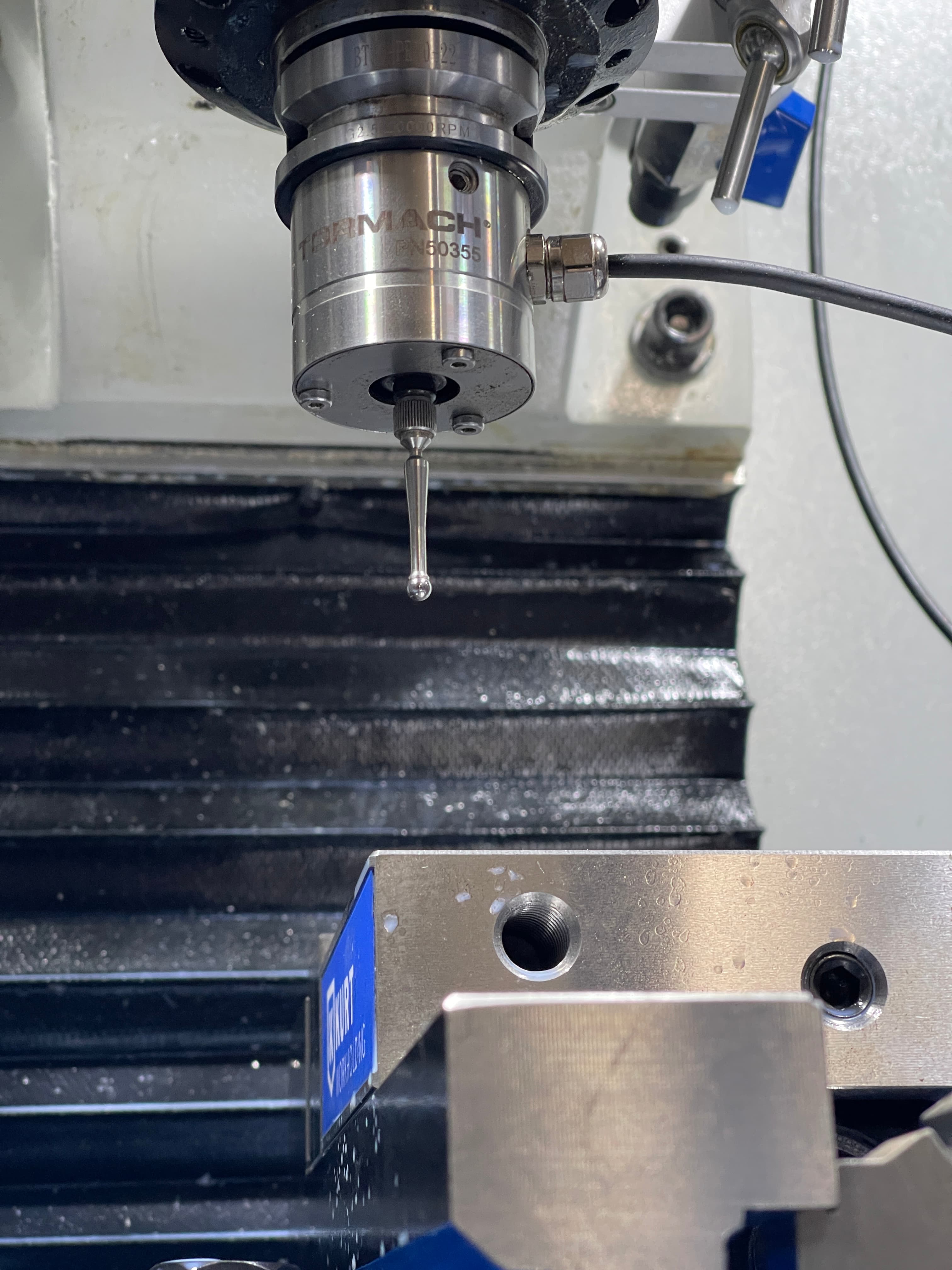
In the holes.
You can tighten about .1mm in my experience. Beyond that you better loosen the other side. More than that and it starts deforming the center pin and I even stripped one of the screws and it was a nightmare to fix. Mostly because it’s really hard to probe when your probe is in the vice.
1 Like
Thanks, Harold. I just wanted to double check - those screws seem to tighten the entire shell of the probe, including the cable gland. They don’t seem to be a sort of fine adjustment?
So if I tighten the screw and hits resistance, do I just torque it down to “move” the probe in the opposite direction?
Wait…am I supposed to slightly rotate the shell clockwise or anti-clockwise to adjust?
The 3 screws push against a center pin so tight moves it a little, more tight deforms the pin. It can rotate on the pin but if the pin is deformed then the screws try to go into the dents and it all starts going wrong.
There is a dance here of loosening two a smidgen them tightening the other. If you just mash it you will likely have a bad day.
Or at least a long one!
I have also found that the first probe touch after tightening is never the same as the second touch. When I calibrate my probe tip I tighten probe all 3 sides and then probe again. The difference between the first and second readings is usually +0.002mm. Also warm spindle and bearings. I have marked my spindle nose and probe tool holder to make sure they are always aligned the same. I need to build an indexing arm to click into the probe to index the whole assembly, but like the other 655 items on the list, one day
I stripped one of the adjustment screws, I couldn’t remove the screws, it was like the screw hole hade a reverse taper so when I unscrewed them they would get tighter and tighter and I couldn’t unscrew them far enough to allow the center pin to escape. There is a little channel on the center pin. I finally drilled through the stripped one and tapped it with a smaller grub screw. Very nerve wracking.
1 Like
Thanks again, Harold. I went ahead and did some gentle adjustment of the screws in conjunction with the Tormach ETS setup probe adjustment routine, and unbelievably, I was able to get the probe to within 0.0002” on all three “directions” of the adjustment screws.
I will say that these screws mystify me and I still don’t really understand how they actually adjust the center position of the probe, but at least they work!
If you really want to understand what’s going on, with the probe on a bench, back out all 3 screws as far as they reasonably go (don’t push it, mine can’t be removed from the outside of the housing - I think intentionally to prevent you from loosing the screws.) an you can remove the 10mm shank from the back/top of the probe body. There is a LOT adjustment available and the design is such that shank stays accurately perpendicular to the probe body while being adjusted axially.
You will of course have to recalibrate the probe tip again.
Or just look at the exploded view I posted in this thread a short while ago.
It’s important to follow the Tormach directions accurately or know what’s moving inside. I originally modified their directions by having the adjustment screw facing me instead of on the back side facing the surface you are adjusting too. This made the screw directions backwards. I also makes it so you are testing a radial contact point that is BETWEEN the two screws on the back. that you can’t see while adjusting. (yes I have a habit of making things harder than they need to be and not following directions).
That combined with the 3 screws working against each other made very easy to just over tighten all of them and end up with poor results. As has been said, you REALLY need to be working all 3 screws slowly and lightly. Only when you are getting REALLY close do you go for a little tighter to make sure it stays in place.
I’ve got multiple probes and also have a speeder head. I need to setup the probe every time I put it in the speeder - there’s no TTS holder. I’ve gotten a lot better at it.
1 Like
Thanks for the detailed response! That was a tragic experience, David. I actually read through your post in my search for knowledge before posting the question, so I’m really glad that you documented everything so clearly.
Now that you point it out, I can see very clearly in your pictures how the probe adjustment works.
I think what was confusing me a bit was the fact that my BT30 holder obscures the top of the probe, but now I can imagine what’s going on underneath those screws.