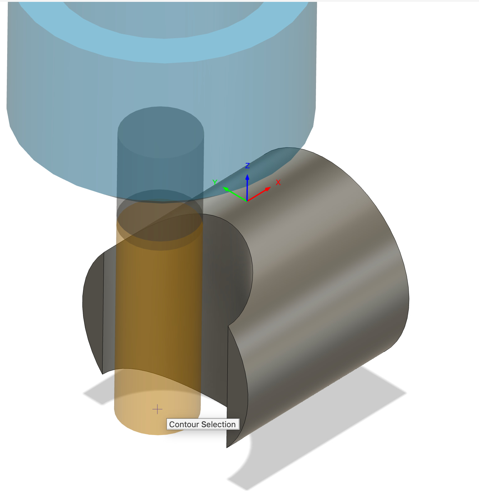
I have a need to mill a curved slope perpendicular to the end of a short piece of round stock between 1/2” and 1” diameter. I was thinking that having the stock perpendicular to an endmill approach would be preferred rather than trying to accomplish milling the same feature using adaptive clearing with a bullnose and then finishing with a ball end with the round stock mounted “normally” in vise soft jaws in terms of it being a simpler operation (it would just be an adaptive clearing and final contour for finishing).
What sort of fixture am I looking for? Completely custom fixture? Take the soft jaws to hold the round stock and turn them into a “vise”? The other issue is having enough clearance for the EM + TTS holder to do the op in this orientation.
Overkill would be a 4th axis (I don’t have) and I don’t need to rotate it. I suppose the equivalent of the round ER collet you use for a 4th axis would be an option or a 3/4-jaw vise mounted to a tombstone or similar fixture?
Ideally, I’d like to be able to do four at the same time. In this case, the best I’m coming up with is a self-centering vise on a tombstone (or equivalent) to get it perpendicular to the mill table and the version of said vise that will accept custom soft jaws that are “thin” and hold the part as far away from the vise as possible in order to have clearance for the EM + TTS.
In terms of sizing of said fixtures, I’m on a 440.
Yeah, that works to do a single prototype but my long term objective is to clamp down 4 at a time to reduce operator intervention per cycle.
I could also cut into the side of the soft jaws near the top and that may have the clearance for the end mill and TTS but then it’s only two per vise or four if I buy another 4” vise and can position them and the tool paths very carefully…
I would make a work holding that bolts to the table. That way you can have them all done at the same time. Or you could get a ball end mill the same size as the radius and use it to finish the part. Or mill the holes in the parts and then mill them in half.
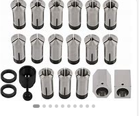
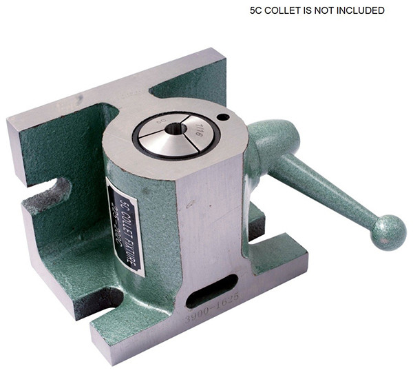
This by far my favorite material holding method for anything under an inch in dia.
You can literally have your way with the material. I like it so much I have 4 sets of blocks, a collet rotary indexer, just about every 5c collet size and type made!
Tormach sells them or they are very common to find
Excellent suggestion. Not sure if I can shoehorn four of those in a vise and clamp them all down but I’ll look into it. I had no idea how they worked and found this video in the archives.
I like the idea of building a fixture that bolts to the table, you can hold and locate the work all in one go, then create a locating feature on it somewhere to set your WCS. It’s a little more work to start but if you’re making these on the regular it’s easy to set up and load. Remind me, do you have a fixture plate on your table? If you do it’s really fast, if not you might be able to hold it in your vise…
No plate (yet). I am thinking this may be the better approach. I could probably make the lower part of the fixture so it anchors via t-slots if not the vise.
Do you have an example in mind of this specific case OR even a good example of someone else who has worked through designing a clamping fixture that I could reference?
Stick “5c mill fixture” into a search engine. Also available in ER and other collet types and gang setups. Tormach has one but it’s vertical only for the rotary table.
Lots of ways I could see doing this. A bunch of collet holders bolted to the table would probably be the simplest to source, though you’d likely have to indicate each one in for the initial set up which could be time consuming. I’m also not a huge fan of collets holders for repeat work because small changes in the bar diameter can lead to significant differences in how much the collet pulls into the block, changing where the end of the part is. You can mitigate that with a stop that is bolted to the table as well, but that’s an extra step.
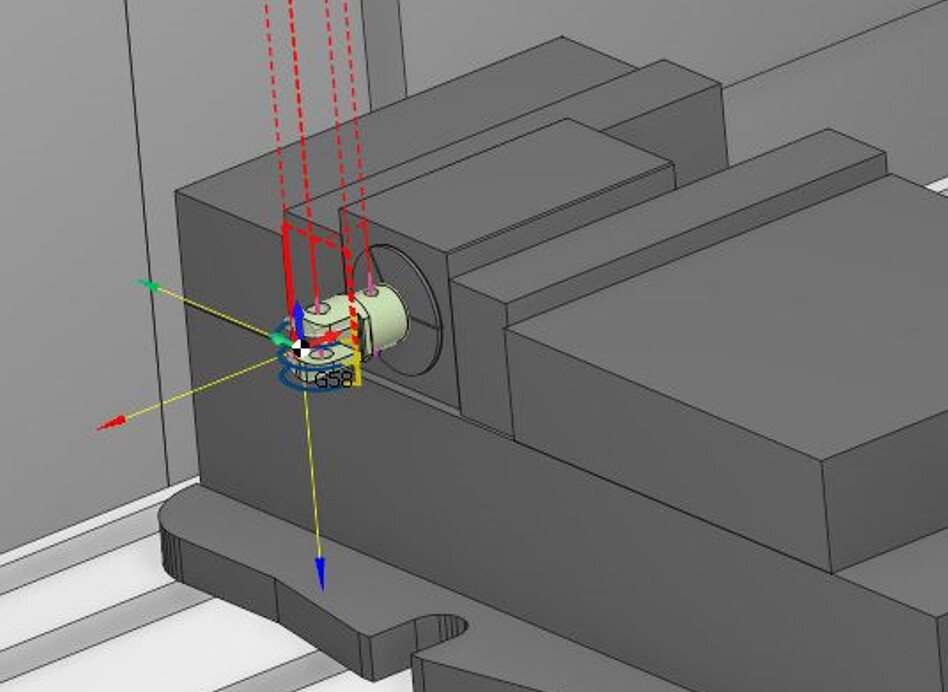
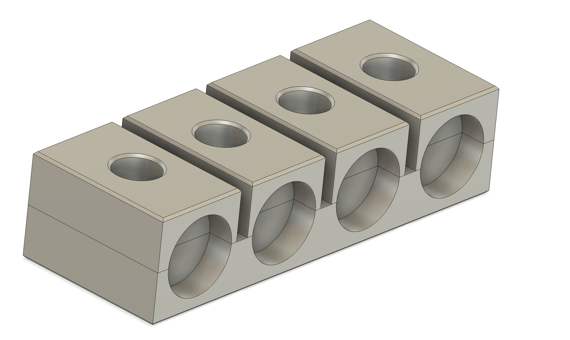
If you plan on doing a lot of these, I’d probably build a quick fixture. I envision a chunk of aluminum, bolted to the table, with 4+ slots (V is probably ideal to compensate for diameter tolerances) At the back of each slot would be a pin or similar to serve as a reference stop. Then another more or less identical block with a few through holes to allow the two pieces to be bolted together. If you want to get fancy you can put a couple springs in between them so the top block opens as the screws are loosened.
Obviously work to do on this but it’s the rough idea, I’d probably use more fasteners and you’ll need to decide if it’s getting bolted to the table or held in the vise. But it’s a thought…
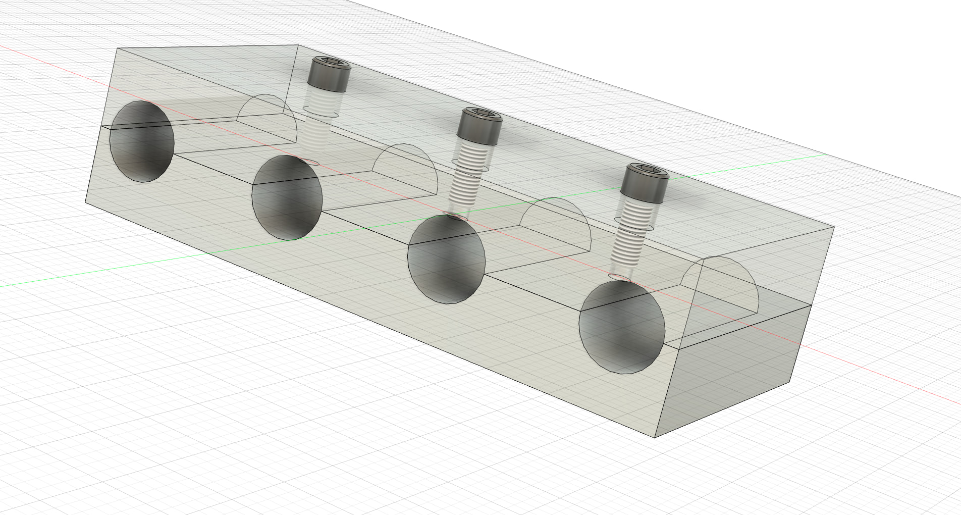
My engineering buddy, ChatGPT, says that you don’t want a long beam like Scott modeled and I originally came up with (my v1 was the same idea, fasteners between the stock recesses). I have recessed socket heads modeled but the idea is to use as large a diameter bolt and as fine a thread pitch to help with “clamping” and to go all the way through the block and thread into T Nuts (or a fixture plate) instead threading the top “cap” to the lower fixture.
What’s ChatGPTs reasoning for ruling out the long beam? I like the separate cap pieces in yours better, I do wonder if a little more space between each and modeling the cap and base with more surface area would provide more friction and better clamping?
With three bolts between four stations it says the outer ones aren’t getting the same clamping force as the middle two.
The way I try to analyze it, each bolt inside of the two outboard stations is acting as a lever but on the wrong end of lever? If there were five bolts that may be better if is a single beam but then you really have to make sure you are torquing to the same value for each…
Thanks. I’ll keep this in mind if the custom aluminum (and then a custom steel version) don’t work out and this widget I’m trying to produce in quantity to sell ends up selling enough to justify that puppy. Just starting out with this idea as a potential side hustle…
The idea that the outer locations aren’t receiving the same clamping force isn’t wrong, but as modeled, the solution you posted isn’t ideal either because you’re now creating a lever with the rear edge of the part as the fulcrum so the diameter of the part isn’t going to see much clamping force. This will cause your fixture to distort quickly (at best) or your parts to come flying out at worst. Not to mention, those super shallow pockets aren’t ideal. You’ll want to seat the parts in as far as possible.
The single beam approach is the better one in this case. Yes, the outer two won’t have the same clamping force, but that doesn’t necessarily create a problem as long as the clamping force is sufficient. However, you could always add an extra bolt on either side of the outer parts to fix that problem.
As for ensuring consistent torque, that’s always a thing with any kind of production work holding, even with a vise. Varying torque affects the position of the parts, if only slightly, which leads to larger variances from part to part. Using a torque wrench every time ensures consistency which will improve your tolerances.