I have recently added a Microarc to my 440 and am having a miserable time getting it do work with fusion 360. It seems that whenever the microarc “A” axis moves, the Y axis also moves. One of my parts requires engraving on a curved surface and the Y axis movement negates anything other than one straight line from being created. Obviously, something is setup wrong. Any suggestions?
Does it work in simulation?
Are all 4th axis movements causing the y axis to move or just the engraving tool path? That could help narrow it down to a config issue or a tool path setup.
I would double check the tool path, especially the section where you set up the multi axis. When I first started this area vexed me while I sorted it out.
In the configuration of your nc double check how you setup the 4th axis.
It could help if you post some screen shots.
This project doesn’t have any engraving in it but it’s the only 4th project I have available ATM. It might help to plunk through there to see how I setup the job.
1 Like
@Todd_Clontz
I was curious so I dug into the last 4th axis engraving project I did.
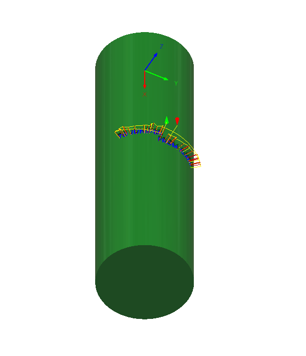
I did a 2D pocket and used the Wrap function.
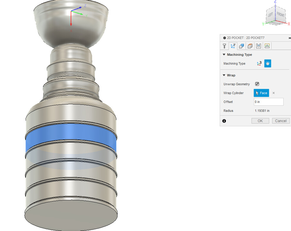
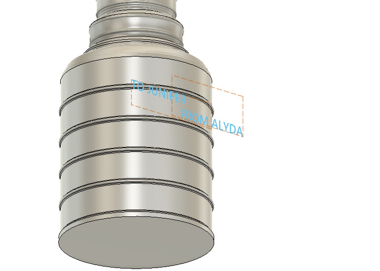
I also didn’t model the lettering, I just drew them as a sketch tangent to the round surface.
Hello again. Well, its September and we are still trying to get this Microarc working properly in fusion. Obviously we have doing other things but really need to get this working. We are trying to engrave cylinders. we need the A axis to rotate and the Y axis to stay still. Every time we post the A axis turns and the Y axis moves to counteract the A axis so all we get is an engraved straight line.
My guess is that the setup is wrong, or we are missing something. We have had it work by using a model and program downloaded from NYC CNC. Works perfectly. Can’t figure out what they did that we haven’t. So, we know it CAN work but have no idea how to GET it to work. If anyone can help out with this it would be greatly appreciated. Neat (expensive) addition to the machine, NO use in path pilot and NO instructions on how to get it setup in CAM software.
Off the top of my head, I’m going to guess that you have it set wrong in your post processor or your Fusion setup WCS. If the NYC CNC program works, that tells me you have your MicroARC setup pointing in X- (microarc on the right side of the table, with material sticking out towards the left side).
When you build your setup in Fusion, make sure that you set your WCS such that the Y and Z zero are somewhere on the centerline of rotation (which should be the centerline of your cylinders). X zero can be where ever you like but I typically put it on the end of the part furthest from the microarc to make it easier to probe. X axis MUST point along the centerline axis of the part.
The other option is your post processor settings. When you enable the rotary, make sure you have the correct direction set. Again, assuming it’s setup like the NYC CNC videos, that means selecting X-. If you have the correct axis but the wrong direction (+ vs -) it will seem to work but your engraving will be backwards. If you have the wrong axis selected (Y vs X) you will end up with a similar result to what you’re describing.
Failing all of the above, attach the file to your next post and I can take a look at it.
Todd,
Have you reached out to Autodesk at all? We try to be helpful wherever we can but ultimately they have the expertise in this area.
Thank you,
Norman
Have you tried projecting the text onto the cylinder in fusion?