Machine Tending with ZA-6 - Working!

I’ve been chipping away at getting my ZA-6 to do machine tending on my Tormach 1100S3 for a while now. It’s been a super interesting journey as I sort of went from being a complete robot n00b to someone who is moderately competent at running the ZA-6 and now has a working machine tending set-up on my 1100.

There’s been a few places I’ve been discussing this around the Internet, but seems like this is probably the right home for the conversation. If anyone is considering trying to tend a CNC machine with a ZA-6, I’m happy to share what I’ve learned along the way.

The starting point is probably this video that shows everything in action, and then you can work backward from that to see what I was up to along the way:

Feel free to ask any questions. Happy to help.

3 Likes

@bigtchopshop Thanks for sharing all this! I’m really excited to see you blazing this trail.

I saw a number of VersaBuilt products in use at IMTS yesterday. This machine demo was using two Multigrip vises (same as in the above video) to do 1rst op/2nd op work on flat aluminum bar:

Is there any 2 op work in your future?

Awesome! Yes. The Op2 workflow on VersaBuilt is particularly interesting because as far as I have seen, almost everyone else defers to pallets/fixtures for Op2. Although the reasons for deferring make sense to me knowing what I know now, it would still be way better to have the robot able to do that Op1 → Op2 transfer, so I think Versabuilt has that dialled.

I’m actually going through this exact thinking right now and there are arguments for both approaches (Versabuilt Op2 vs. Pallet/Fixture Op2). And. realistically, the answer is you probably need both depending on the mix of work. I am a job shopper, so it’s always high mix / low qty.

This is my current thinking:

Pros of Versabuilt Op2 Approach:

  • Assuming you’re doing fairly conventional 2-Op parts, this is a path to basically fully autonomous “one and done” parts going on and coming off the machine. In my job shop, a surprising number of parts would be totally fine with this workflow and come off the machines basically “done”. So, that’s strong.
  • Once you’ve already invested in the VersaBuilt system and the robot and CNC programs to handle it, then a reasonable amount of the extra effort to do Op2 stuff is sort of “cut and paste” or, at least you have a workflow and process to accomodate adding it to your code.

Cons of Verabuilt Op2 Approach:

  • The soft jaws are relatively complex/expensive compared to conventional fixturing. You could probably stretch them out a long way by putting intermediate fixturing, or a sacrificial surface on them to be able to re-use them for multiple parts. Or, for bonus marks, write a full-auto robot/mill program that makes them so you can make your own whenever the machines are idle.
  • You’d end up training and maintaining a second vise position, which would double your set-up overhead if you end up bumping out of position at some point. This isn’t terrible once you’ve got things set up as it happens infrequently. But, when it does, it’s no fun, and less fun with 2 or more pick up points.

Pros of a Pallet Based Approach

  • The robot does the same thing day in and day out - load pallet. Training and programming wouldn’t ever really need to change much. You have X pallet stations trained for pick up and however many bases trained on the machine and that’s that. Likewise, I think training could be a bit easier as it’s not as delicate of an interface to land a pallet onto a zero point base as the VersaBuilt jaws.
  • Supports more than a 2 Op workflow (albeit with manual loading and additional fixture overhead)
  • Ultimately, you could get pretty fancy with having different pallets set up for different jobs and the robot and CNC shaking hands on what GCode to run on each pallet with a bit of a scheduler and some macros. So, for a job shop running lots of different jobs, this gets interesting.

Cons of a Pallet Based Approach

  • Way more fixturing overhead, thinking about fixtures, clamps, pins, Mitee-bites, etc.
  • Requires human intervention to load and prep each pallet, so does not scale without humans.
  • Depending on the system, pallets and hardware can be expensive.
  • Payload weight also starts to become a factor. Even a small pallet can weigh a couple kg, so you need to be wary of pallet+workholding+part weight from a payload perspective.

Somewhat apples and oranges though depending on the use case. If you’ve got 100 of the same parts to run, that looks different than running 10 batches of 10 parts. So, that’s sort of why I say there may not be an alternative to being able to run things both ways.

One thing that would potentially be kind of neat would be to machine the mechanical interface from a set of Versabuilt Jaws into the side of a pallet… so that you could also pick up pallets with the VersaBuilt jaws and be able to mix and match if you had both a VersaBuilt vise, and some sort of zero point pallet base on your table.

hello so i am a new user of a za6 robot and a 1500mx mill i am not a python programer i wonder if anyone out there has a sample robot program that i could use to try to build a program for loading machine parts from a grid i hear the lidar will be comming but my boss is looking for results now. i hace a peg oard as a grid base with 3d printed pegs to locate my parts wvery 3 inches

@tony_szklany

Attached is a zip file containing two different programs showing ways to program a grid. I wrote these some time ago for a friend. Code is commented, I think you will understand this just by reading the code and comments.

Both programs create and apply a user frame so that the grid positions are sensible, e.g. they use X=0, Y=0 as the lower left corner. I included a little illustration that you’ll see when you run the code (make sure to copy all files in the zip to your controller before you run the code).

One program is simple, just loops through a 3x3 grid. One execution of the robot program’s main loop will move the robot through all 9 grid stations.
The other one is slightly more complicated. Each execution of the main loop moves the robot to one of the 9 locations. The main loop needs to execute 9 times to get through the whole grid. Each time it arrives at a location, the grid position (e.g. 0,1) is saved to a text file. This approach is more complicated, but:

  1. It might make the code you need to execute after arriving at the station more straightforward to write
  2. It “remembers” where it was, in case you need to restart the program part way through the grid.

I hope that helps you get started.

examples for John.zip (4.6 MB)

Well making a lot of progress machine tending our 1500mx with a za6 robot

1 Like

Fantastic! Nice work @tony_szklany .

Im having some issues setting up my tool frame so that i can zero the numbers so that my first part on the grid is x0y0 the example you helped me with is great but im having trouble understanding setting a frame that works with my end of arm tooling. My video was a “brute force program” but i want to refine it so it is easier to matain and change with different parts. And help would be much appreciated .

@tony_szklany - here’s a condensed version of my general advice on machine tending with a focus on tool and user frames.

Wherever possible, use joint-type waypoints.

Until I get to a move that will require cartesian coordinates, I prefer to use joint positions. They are 100% deterministic, always plan quickly, and aren’t affected by tool or user frames. This means there’s a reduced chance that you’ll crash something while setting things up. We use joint waypoints for the sequence of moves through the enclosure door. We also use joint waypoints for the ‘safe move’ to a clearance position above the first pick point. I only start using cartesian waypoints for the actual pick or place positions.

When you need cartesian waypoints, specify the arm config, and train your frames so Z is always up.

For the “last mile” moves (e.g the last 50-100mm long moves that make up your picking or placing sequence) you usually need to use cartesian waypoints. Cartesian positions allow you to handle actions programmatically (e.g. same approach/grasp/retract routine repeated over a grid), allow you to pick from the same point with two different grippers, or allow you to make small alterations to a single frame without having to retrain a bunch of waypoints.

When creating these waypoints I always specify an arm configuration (e.g. NUT, FUT, etc). This makes the motions between these waypoints deterministic.

I prefer to write my cartesian waypoints for picking or placing such that XYZ zeros correspond to the point exact point where the “pick” or “place” happens. For a pick waypoint and an above-the-pick waypoint I might have:

pick = p[0, 0, 0,180, 0, 43.257]

clear = p[0, 0, 100,180, 0, 43.257]

Notice that there are some ABC rotations in these waypoints – more on this later. Lately I’ve gotten in the habit of only creating the pick waypoint with XYZ = 0,0,0, and then using an incremental move to handle Z approach locations.

Importantly, when creating user and tool frames, I have found it easiest to create them in a way such that Z positive always moves the robot “up” and Z negative is always “down”. Of course, you can handle this in different ways, but I find that it messes with my mental model when my ABC offsets for either tool or user frames end up such that the robot moves any direction other than up when I jog using the pg up button.

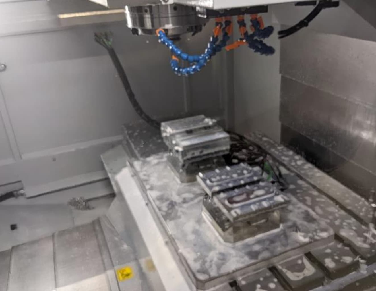
Because you have two grippers, you will need two tool frames. Because you have the grid for picking from and the fixture in the mill, you’ll need at least two user frames. If your tool frames are trained perfectly (the physical geometry perfectly matches the tool frame offsets) you can get away with those four frames. If getting those tool frames “perfect” is a challenge, you can cheat by creating extra user frames for the combination of, for example, gripper A with the mill fixture and gripper b with the mill fixture.

If this helps, fantastic. If you’re still stuck, reach out again and I can try to be more specific.

thanks for the help. i can see where joint waypoints are an advantage and will use them in the future to enter and exit the enclosure . i adapted the simple example program you suggested added a subprogram and it runs beautifully i enclosed 2 programs a 9 position long program i shot a video and a version using your simple grid with more parts now 45 on the table the program went from 10 printed pages to 2 so much easier to work on. the thing i cant seem to gram is how to train the user frames (i copied yours and adjusted) i have watched your u tube videos and i just cant get it taught the way i want (my z in user frame 1 is upside down). but hey at this point i get 5 parts an hour so 9 hours running . Still waiting for the harness to confirm by input the door is open our was not working as we received it next i plan on modifying the end of arm grippers so i get more reach closer to the robot base. if you have any thing else on user frames id love to see it. also the 1500mx runs the part in half the time our haas super minimill did so well done on the machine and robot.
Mach 3 and the MaxNC 10 Open Loop.pdf (393.4 KB)

1 Like