Alex,
Apologies! The pinout for those connectors is more clearly described in the earlier schematics. We could have done better with that section on Rev 5.
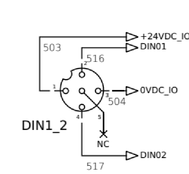
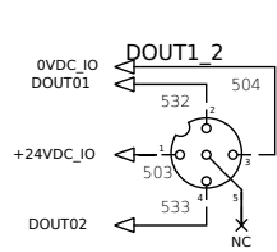
For both input and output connectors, pin 1 is 24V and pin 3 is ground. For the inputs, applying 24V to either pins 2 or 4 will cause an input to go active in the software. For example wiring a switch from pin 1 (24V) to pin 2 (digital input) will cause that input to go active when the switch is closed.
For the outputs, toggling the output in the software will apply 24V to pin 2 or 4 (depending on the output number selected.) That 24V supply is stiff enough to drive an LED or a relay or contactor coil, but not more than that.