Help with Micro Arc work offsets

Ok here is round 2, I did 2 tests tonight with the same failed results. WTH is going on here? The procedure totally makes sense to me now after doing it a few times. IS there something you’re forgetting to tell me? Is it possible that Im doing something different than you might be doing since Im using a probe and you’re not? IS there an initial step Im not doing?? This should work, LOL!

Before I start, I level out the fixture or part with David’s script. My 1st hit Im using probe Y- set work origin, 2nd hit Im using find Y+, 3rd hit Im using find Z.

1st test probing off the fixture, here is the results. Same as before. :roll_eyes:

2nd test to verify if there was something with the fixture causing issues. Not the case as you can see I did this one in the self-centering vice with stock that has been faced on all sides.

Is the script supposed to move the probe to the center at the end of probing? What your showing looks like where the probing script ends and parks the probe. Or the last photo is your showing is where 0,0,0 is calculated from the probing?

Something in the math
When you use the built in probing cycle to find center of stock on the center pin in the A. Can you compare this data to compare against the second script that you are using?

Not sure why you aren’t using the built in A-axis find stock center,(or if you are) , but it seems to me in a lot of these “can’t get probing right” problems there is something about the origin isn’t copied, or saved to the WCS that the script uses. That seems to be a frequent problem with the probing scripts.
It’s something only people that write probing scripts can detect.

As soon as you throw a probe routine in the mix, I can’t help. I don’t have one and have never used one. I have a haimer in my machine. Effectively a fancy edge finder. The procedure I described is exactly how I find my center of rotation using the haimer (or a standard edge finder) so it may be different than what one would do using the probing routines.

1 Like

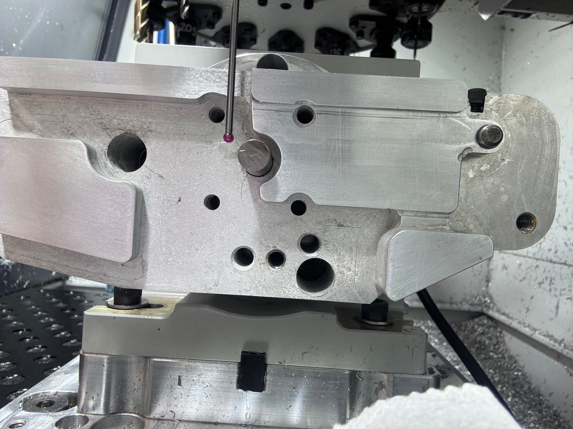
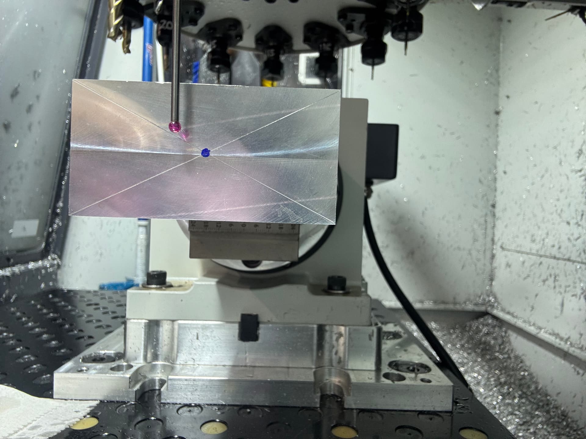
All the probing routines Im using for Ian’s procedure are all basic Path Pilot routines. The positions the probe tip is in, in the pictures, are from me using GOTO Z0 Y0 manually by entering into MDI after I have performed all the steps in Ians procedure.

Sorry to write a book every time and sorry if some of this is redundant but just trying to cover all the info and address your guys input. I do appreciate the input.

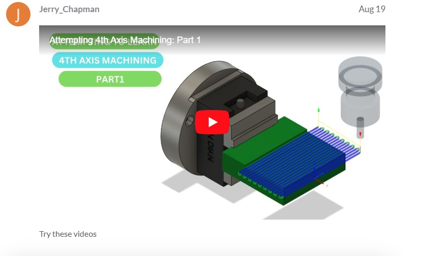
My original plan was to do just that by following the video in the screenshot below and David Loomes scripts. SO, the reason I’m not using the built in find A center is as I understand it that “could” introduce additional variables in accuracy in my final setup. You even suggested this previously in one of your posts to me in the fact that swapping out fixtures in a single set up could introduce positioning issues down to the play in the screws. You did not say exactly that BUT it stopped me in my tracks making me realize that “could” be a bit issue. The reality is swapping out multiple fixtures in a single set up is the issue, RIGHT???.

As described before the G59 setup requires several steps as described here.

1. Perform Path Pilot find A center script by using the Tormach ER-40 faceplate and 1” precision gauge pin to find the center. “ALL GOOD”

2. Store this location in the control as an alternative work offset for the Micro Arc (I used G59) just like in the video. Watch the video if you have time, its 2 parts.

3. But then I need to remove the ER faceplate and replace that with my fixture, SO that is the problem with going that route. IF there are any inaccuracies in my fixture in “relocation onto the micro arc” I’m screwed. RIGHT? For me, absolute position is necessary to be successful in making this part. I’m not only making a few of these and I need a repeatable setup for now and the future.

4. The saved G59 location makes it easy for future recall of the Micro Arcs center, and makes perfect sense for machining on “raw stock” from scratch, BUT could be the kiss of death for a previously machined part going in for Op3, RIGHT???

5. SO when Ian suggested this procedure, it made a lot of sense to me for the fact that I could do the set up from beginning to end with “my fixture” already mounted to the Micro Arc.

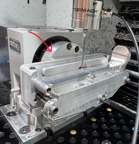
Here’s a thought, Kind of a crazy one, yesterday I started thinking about using the outer diameter of the Micro Arcs mounting ring OR the GTM adapter plate shown here with arrow as my probing surface and running the Path Pilot (probe A find center) I checked the clearance in CAD, and it looks good. Quesion is, if the OD would be mounted absolutely concentric to the Micro Arc’s center. ??? I even reached out to Steve Strange of GTM Manufacturing to get his input on the OD probing, have not got a reply yet. IF there is clearance, I could do this with my fixture mounted and I would be good to go. I have my doubts the OD is a good option to probe. I guess running an indicator on the OD would tell the story right?, I did not think of that last night. WHAT do you guys think of this method? It would be a simple solution for future milling of this part for sure!

Bill,

It seems to me the center of rotation is the center of rotation regardless of the figuring added to the MA after the fact. I think if you simplify this to a simple part you could prove this out and then move to your intended part after. I set the center of rotation using the built in PP routine and storing it in G59. After that finding the parts X, Y&Z are next. X is pretty easy I use the stepped face of my self centering jaws or what ever fixture I’m using. Y & Z in the case of this (mine) part are on the center of rotation. I just find Y+ and Y- then /2 as you’ve already done. For Z you could do the same thing. I think the odd shape of your part makes it more complicated to visualize. That’s why I wonder if you shouldn’t put the WCS on the fixture and then joint the part to it in CAD. Sorry if I’m covering old ground here.

In this pick the arrow is point at the extra stock I have to provide clearance and space for the vise jaws. My MA is on the right side of my machine.

1 Like

Thanks for the input,

What is your setup for performing the Path Pilot Find Center of rotation? Are you using the ER-40 adapter plate with a precision round bar or gauge pin??? A 3 jaw chuck??? Are you then changing to another work holding or fixture to mill your part/s?? AND in your experance have you done this with previously machined parts where everything needs to be in the right place. This is the point that’s tripping me up based on some of the warnings here have been in regards to misalignment down to the screws themselves. AND, do you ever have issues with misalignment OR worse your 4th axis work not being in the correct location? THAT’S a big one for what I’m dong. IF my top-to-bottom pockets are off, its game over.

To clarify, my work offset is here. Do you still feel a benefit to setting it on the main fixture body after seeing this? X is on that outer face and is accessible to the probe when the part is in the fixture.

Could you elaborate on your probing using “find Y+ Y-“? Are you saying you’re only using find at both ends and not setting an origin at the 1st point?

The center of rotation should not be part or fixture dependent to my way of thinking. It is the center axis of the MA “spindle. What ever you attach to that spindle will rotate around the center of rotation. Whether that is a collet chuck, a self centering vise or a 3 jaw chuck, as long as your MA goes back in the same “exact” location each time. I have a Saunders fixture plate on the mill table and then the sub plate for the MA.

Is the small circle inside the bigger circle what you are calling your WCS? Where are the axis arrows?

Yes I would still investigate probing of of the fixture as long as you are confident the part is in the same place every time within your acceptable tolerance. Is the part your machine work or is it a casting your getting?

On probing Y I would go to the front of the work and probe Y+ and set origin, the go to the back and find Y-, that gives you the length divide that by 2 move to that location and that is you zero or middle of the Y.

I hope something said here helps…

Yes that is my work offset, I was in design when I took that screenshot.

Forgot to add this.

Yes the part is my machine work from billet not a casting.

In regards to the probing you explained that’s exactly what I’m doing, but I started at the back of the part. Im going to do a test tonight on a 123 block and see if my centers are correct.

1 Like

I usually start from the back to but I was trying to figure out the easiest way to explain it. Front to back aligns with the probing screen screenshot a little better. Let us know how you make out.

Center of rotation and part location are different topics and need to be handled separately.

The center of rotation doesn’t change just because you changed fixtures. But your part location RELATIVE to the center of rotation might.

Your program needs to be built based on the center of rotation but your model has to be located digitally in the correct relative position.

All that is to say that you’re doing an awful lot of probing but not actually setting yourself up for success from what I can tell. My approach to finding center of rotation works great with raw stock or previously machined parts with plenty of extra material to remove or a repeatable fixture. If you’re machining in process parts, with minimal rest material, on a fixture that isn’t very repeatable, no amount of probing will get you a good part. In that case, you need to find the center of rotation using any appropriate method. Then you need to probe a definable surface on your part in the fixture and note it’s location in Y and Z relative to the center of rotation. Then you need to MOVE the part in your model to that same location, regenerate the toolpath, and start cutting.

Now obviously this is a terribly inefficient process unless you’re only making one. So the real solution is to create a fixture that locates on the rotary repeatably, and locates the parts repeatably.

The first half is fairly easy. You can gently snug the mounting bolts and tap the fixture around just like tramming a vise. Ideally, the mounting surface of the fixture is round so you can put an indicator on it and check for runout while spinning the rotary. Once that’s dialed in, set your A0 with the fixture horizontal and you’re good to go.

The second half depends on the parts and how repeatable your previous operations are.

2 Likes

I’d use the pivot pin and takedown pin holes for the fixture locating pins. They are easier to probe accurately and IIRC those are the original datum holes anyway. As Ian says, you just need to know where your fixture is relative to the rotation axis.

IME the MicroARC is not particularly rigid, so you’ll need to watch for that too in your fixture.

Hey Guys, A quick update on my progress. I think im over the hump on this and have a good understanding of how to get set up for the MA and the necisary steps needed I needed for this type of setup. A BIG thank you to Scott Dube for taking the time to talk to me yesterday and help me confirm my setup, which was a big help for my confidence.

I set up Path Pilot to find the center of A rotation with ER-40 Faceplate and 1’ precision gauge pin, attached my fixture and part, then David Loomes Probe A to level the part/fixture perpendicular to the end mill/table. I now understand, I will need to do this each time I set up this part for milling and can not rely on the stored G59 Micro Arc location. Just to point out Im on an 1100M machine (steppers).

So the next step was to test mill with one of my 3D prints to verify that everything seemed to be milling in the correct locations. It did this, and this was a perfect method for verifying everhing was correct. Shout out to Scott for the suggestion, great idea. My son had suggested that as well. I was going to print a solid one but this turned out to work very well cuz the cutters are not really even touching the plastic, other than some flex in the plastic part from being clamped in my fixture.

I verified all indexed sides of the milling on the 3D print, and that gave me the confidence to go in for the kill and run it on the actual part. So I was able to mill, I’d say 75% of everything. What I could measure looks ok, but the proof is when the part comes off the Micro Arc and is inspected. AND ultimately built out to a functioning airsoft gun for testing. Will post pics when I get it done.

Thanks Again, Scott! :+1:

1 Like

Ian, Thanks again for all the input, much appreciated! I do plan on getting your process down so I know how to do it.

Per my post above, I think im out of the woods. Just 2 probing routines for my setup. In regards to your input, Ive worked towards locating the fixture for repeatability from he start. and yes, everything is built and programmed on the Micro Arc’s center of rotation and my X is the outermost surface in X+ to locate it. Time will tell the tale when I inspect the part.

Keep you all posted.

1 Like

You’re welcome, happy to help. You already knew what you needed to do just hearing yourself say it sometimes makes it possible to get the confidence to take the next step! Congrats on moving several step towards getting your part machined the way you want it!

1 Like