Help with Micro Arc work offsets

Hey All,

As a continuation of this post Im still working on wrapping my head around indexed 4th axis work and very close to milling my Op 3.

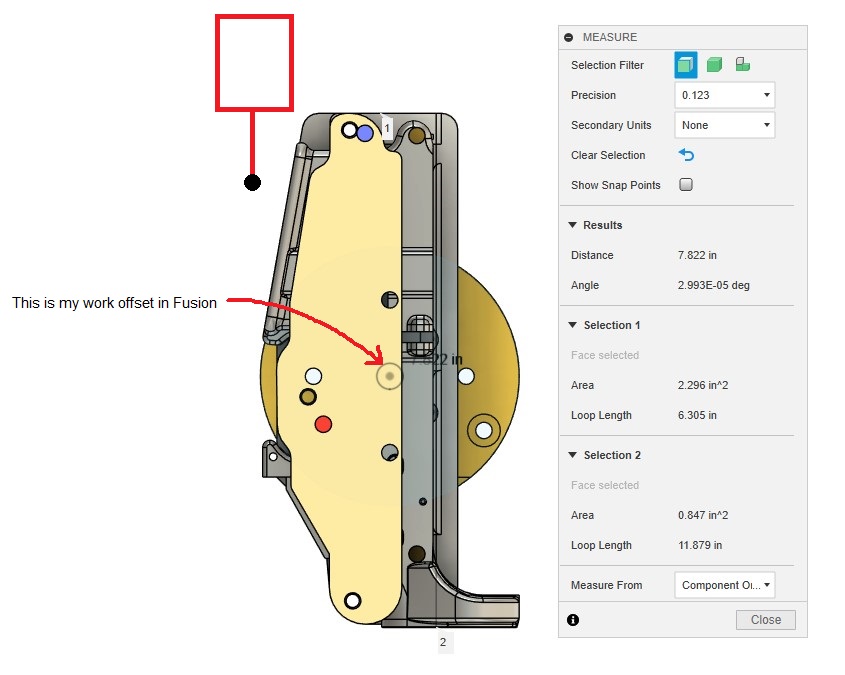
The video Jerry_Chapman posted does a great job of walking you through the process of setting up Micro Arc for indexed 4th-axis work, but does not go though a key detail I need to know about. In the video, he runs the (Find Rotary Axis Center) path pilot probing routine and stores the work offset as an alternative permanent work offset as G59 for use in future Micro Arc setups, which is great!

Next step is to use David Loomes probing script to make final micro adjustments to the Z & Y Micro Arcs center of rotation to compensate for our limit switches not being perfect. Also great!
Then we run David’s Probe_A Z&Y script to make the rotational adjustment to get our part and or stock perpendicular to the tool face. PERFECT!

BUT

What I’m unsure about is how do I reset up after I reboot the machine using the stored G59 work offset and be ready to mill?? He does not get into this in the video. I’ve done it, but I want to confirm I’m doing everything correctly.

Here is the procedure as I’m understanding it.
• After I reboot the machine, I home XY&Z as normal.
• DO I NEED TO HOME A? OR I assume it really does not matter per the next steps.
• I now bring the machine into G59 work offset and command the machine to GOTO Z0, Y0.
• I do NOT move the machine axis.
• I now go back to G54 as this is the offset my part is programmed in for milling my Op 3 work and ZERO out my Z & Y position from the last step. This will now put me in G54 center of rotation for my A Axis.
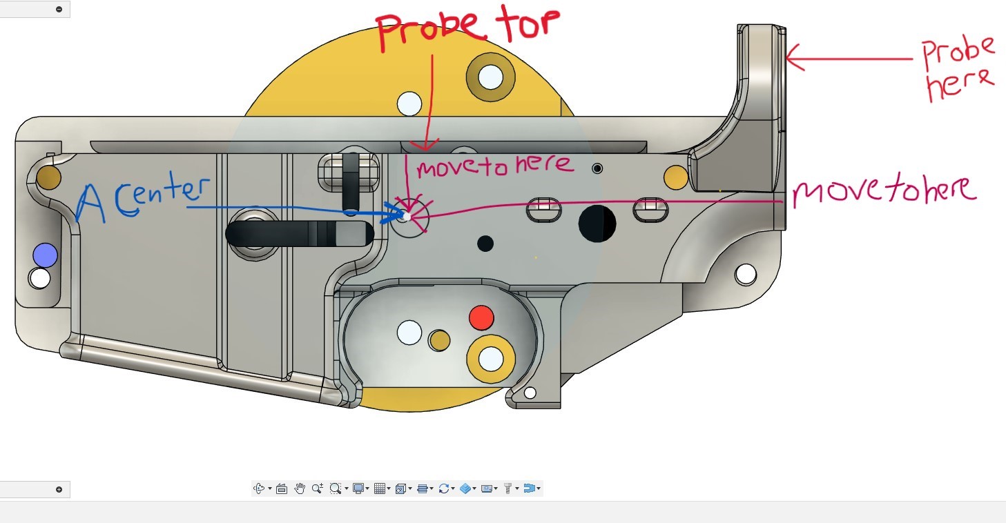
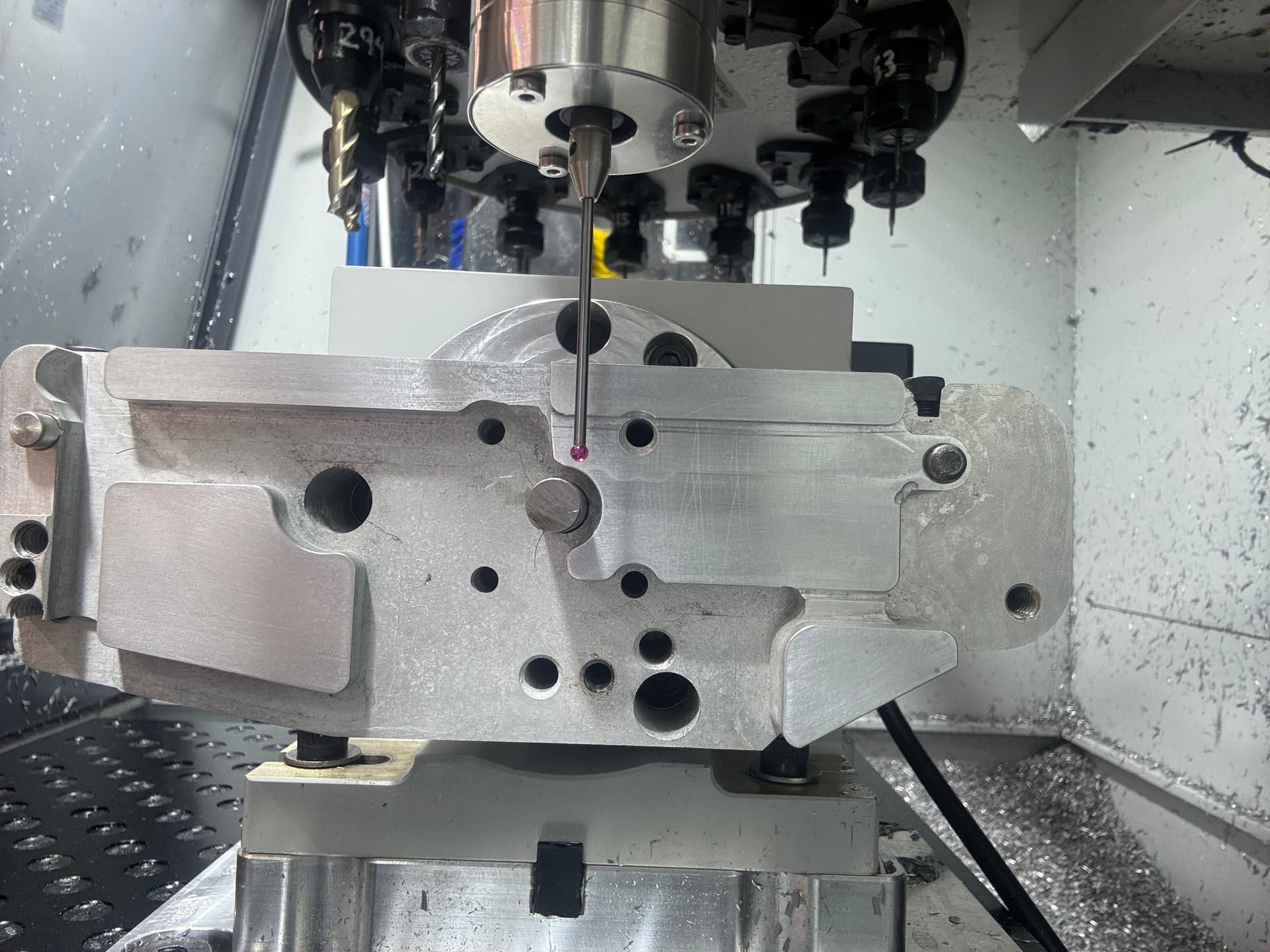
• I now run the ProbeA_Rotary to make the rotational adjustment to get my part & fixture perpendicular to the tool.
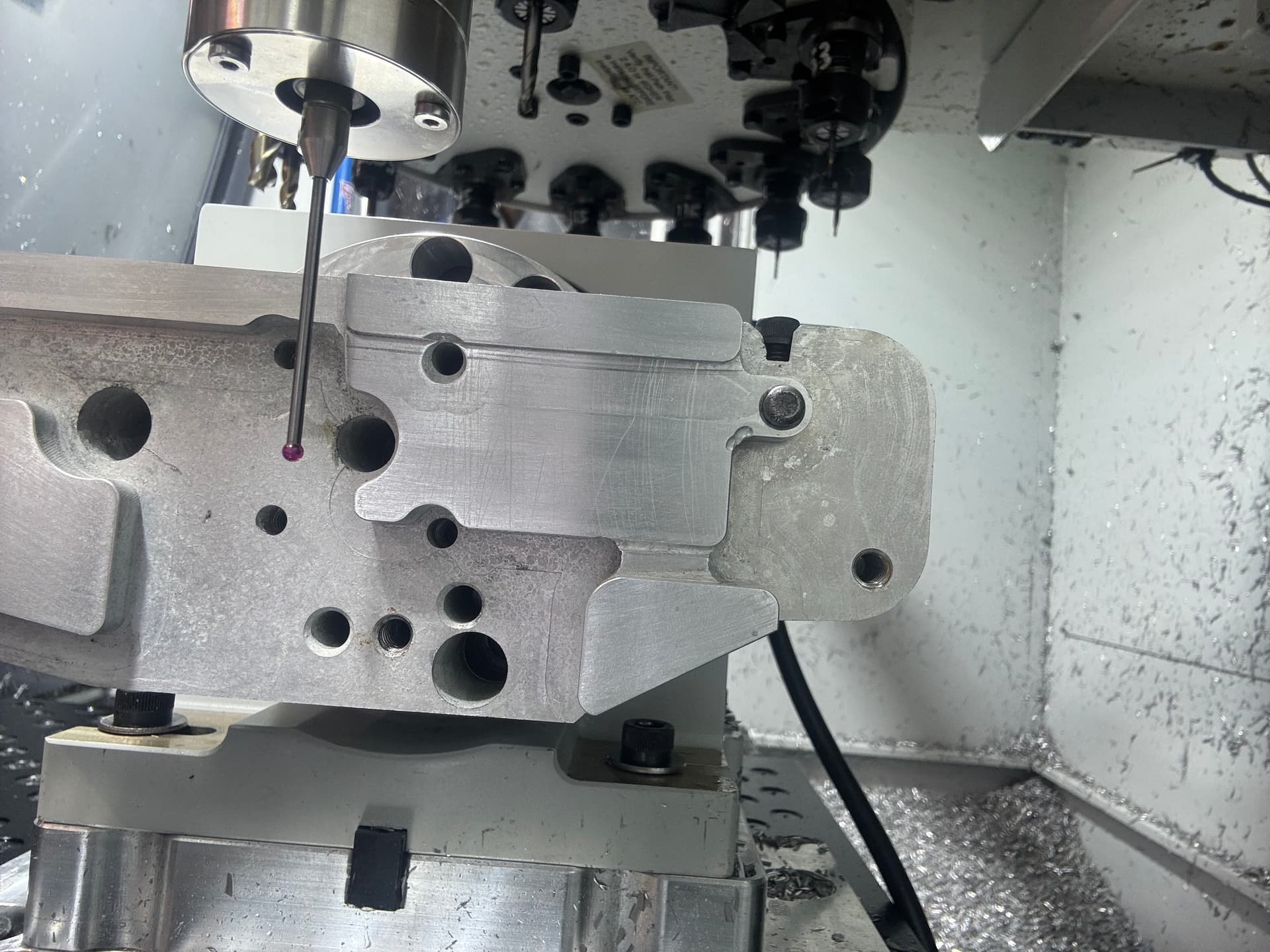
• I now probe my part face in X and I’m ready to machine.
• Does this sound right? Am I missing anything?

QUESTIONS

Once I reboot the machine and preform the above steps, do I need to rerun David Loomes Z & Y micro switch adjustment script to adjust for the micro switches? I think I do right? Any time you reboot the machine and home the inconsistencies of the micro switches are in play, right? And WILL require adjustments, Right?? OR would the Saved G59 be perfect???

Here is where it gets tricky for my setup, sorry for long explanations here.

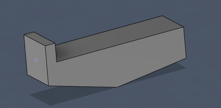
Since my fixture and part is like 81/2-9 inches long I can not run David’s ProbeA Z&Y script with it attached to the Micro Arc.

SO I would need to take my fixture off the Micro Arc, and replace it with my self centering vice and a small enough piece of stock in order to run David’s Probe_A Z&Y script. Im thinking I woudl use a no hole 123 block for this since all side are perfect and In theory would yield better results than a unmachined stock.

For a clearer picture of this watch Davids Video. (7 Min video if you have not watched it yet)

Additional input welcome.

This will crash your machine into the center of micro arc stock. I now bring the machine into G59 work offset and command the machine to GOTO Z0, Y0.

once you change fixtures you are not going to be on the same center. There is a little play in the screw holes. And even using a dial gauge and taping the fixture can only get you as close as the runout of the fixture. You need to index on the fixture you plan to use for the operation, and a self centering vice never ends up perfectly centered.

Also when you reboot and reference the A, all it does is copy the number from the reference column of the work offset page into the A- dro unless you are using the reference kit (which probably is t accurate enough for this) I reference my A- by puting a machinist level on the table and then on the a-axis 3 jaw chuck jaws and match the bubbles. It’s accurate to about .01mm. Then to get more accurate you should be able to run that first leveling script from the video.

Also you could always put a riser under your micro arc so you can go all the way around.
If you need real reapatable numbers I think you will need to put 3 index holes in your fixture. Even this can be difficult though. H7 reamers and hydraulic chuck is the easiest way.

Sorry I know this is kind of fragmented but I did t want to not post the is.

You really need to understand the geometry of the work around the A axis and how any misalignment affects how the work will be out of position. Then build the tolerances in to accommodate that and see if it works.

1 Like

The micro arc holds its position without power really well unless you have a large offset weight. Even then, I wouldn’t really expect it to backdrive given the reduction ratio involved. The offset weight would likely have to be more than the machine can safely support anyway. That said, if you run it to A0 before shutdown, you should not have to re-reference the rotation after a power cycle.

You should ALWAYS re-reference your center of rotation in YZ and your X zero after a power cycle. The microswitches are pretty ok and the MX machines are a bit better about consistent homing, but (and I actually did quite a bit of testing on this for curiosity’s sake) the MX home will drift a few tenths to as much as a thousandth or so and the stepper machines can be up to a couple thousandths. If a chip lands in the wrong place or the rubber bump stop on the lead screw gets worn (or falls off as it did once on my machine), you could end up being WAY off.

1 Like

Hi Harold,

Thanks for the input, I will reply to your input with some more details.

This will crash your machine into the center of micro arc stock. I now bring the machine into G59 work offset and command the machine to GOTO Z0, Y0.

When I wrote this not sure what I was thinking so I will clarify what I did over the weekend when I actually did this. I did not use GOTO for both axes at the same time.

I first jogged far away from my Micro Arc, raised Z, and used GOTO Y0, then zeroed out my Y DRO.

I then jogged very far away from my Micro Arc in X and used GOTO Z0 and then zeroed out my Z DRO.

Also, you could always put a riser under your micro arc so you can go all the way around.
My Micro Arc is on a 1" riser; you can see it in the picture. SO I can rotate the fixture and part full 360 degrees.

You really need to understand the geometry of the work around the A axis and how any misalignment affects how the work will be out of position. Then build the tolerances in to accommodate that and see if it works.
Im well aware of how even the slightest misalignment will affect the final machining location for all features. I keep thinking if Im within + - .003 I should be good. We tested 3D printed parts, and they worked fine. My Prusa XL outputs are within .001-.005.

I guess the only way to find out how accurate my fixture is, I just need to run the 4th axis op and see where Im at?

SO, swapping out the self-centering vice to the fixture just sounds like it’s not going to work, right?
Wish someone could just tell me how I need to get this set up done? It’s making my brain hurt, LOL!

What probe stylus is that? Mine is much shorter and often may I say inadequate :slight_smile: I would love to pick one of those up. Is it a Tormach sold unit or did you get it somewhere else?

Thanks

Here you go, new link

https://www.amazon.com/gp/aw/d/B07G88YKK3?psc=1&ref=ppx_pop_mob_b_asin_title

1 Like

Thanks Bill but the link doesn’t work, it opens my orders. I think if you click on the item within your orders it will give you a link we can see outside of your amazon account.

Thanks!

Scott, I just reposted a new link, same post above.

1 Like

Thanks Bill!, I think I backed into it last night but we’ll see!

Guys, since I can not use David Loomes Z&Y probing script to set my Z0 Y0 center of rotation, can you give me thoughts on this to place my Z0, Y0 center of rotation on my Micro Arc.

BTW: I did not mention before that the lower is located to the fixture on the 1 tare down pins.

  1. Boot up and home as normal.
  2. I run David Loomes (ProbeA_Rotary) to adjust the rotation of the Micro Arc to get the top of my part perpendicular to the tool face. I probe the pre-machined top surface of the part, NOT the fixture.
  3. I now probe that same top surface of my part in Z, and then adjust my Z by -0.65775996 in. and zero out my Z DRO.

  1. I now probe the pre-machined surface of the buffer tube surface.
  2. I now move my Y +3.82150784 in and zero out my Y DRO.

I now probe my part in X per my CAM origin and Im ready to mill.

RIGHT? :thinking:

IS this the solution, or is there yet again something Im missing?

As I don’t have a probe, I don’t know anything about the probing routines so I won’t comment on your posted approach.

Instead, I will tell you how I find XY center. Ymmv but this works really well for me regardless of the setup or material.

Touch off on the part on the Y- side. Zero Y on that point.
Rotate the part 180 degrees. Touch off on the SAME point (now on the Y+ side). In the DRO, divide the Y value by 2. Your Y center is now set. Make a note of the value shown in Y after dividing, you will need that for the next step.
Rotate the part -90 so that point is now pointing up. Touch off again and set Z DRO to the value from the previous step. Your Z center is now set.

1 Like

Thank you for the input and knowledge on this one. A couple of questions on this method, and yet again another road block OR maybe im missing something in the explanation.

¡ Does this method take in consideration and compensate for the fact that the limit switches are not perfect?

¡ For step 2 when probing the +Y side are you saying I should do the calculations inside the DRO or can I do it manually and just enter the number?

· I’m not at the mill right now to try this. I’ve not really done formulas and calculations in the DRO so tell me if this would be correct. Say the 1st probe point in -Y is -3.911 would this be the correct way to enter the calculation in the DRO (-3.911 / 2) ??

Problem OR Im I missing something in your direction?

The part and fixture measure 7.822 long so If I rotate the part -90, pointing up I can not probe the last point or anything beyond the length of the probe tip as my probe tip length is only 2 inches. Alos the bottom profile of the part is not flat like it is on the top thus further complicating any probing.

1 Like

The limit switches aren’t relevant because you’re establishing a new WCS. The only time the limit switch error becomes a problem is if you power cycle the machine and then try to start a program without reestablishing your zeros.

The calculations can be done in the DRO or elsewhere, but I find it easier and less error prone to do it in the DRO. Simply click in the field, and type /2 after the value shown, then hit enter.

I think you may be misunderstanding the method a bit. I’ve attached some (very crude) images to hopefully explain better. The idea is to touch off on the same point in every orientation. The specific point isn’t important, as long as it’s accessible from all three orientations. By checking the same point in 0 and 180, you’re finding the exact Y center of rotation. Then checking the same point again in 90, you have a established reference to the center of rotation but now it’s oriented in Z allowing you to set the Z center as well.

Note the highlighted point in all four images. Again, this can be ANY point on the part, as long as you can access it from all three orientations.

2 Likes

@Bill_Barschdorf is there a way you could probe your fixture instead of the part? since it’s got less contours to it it might be easier as long as your confident about the part locating within your desired tolerances.

Got it, this is perfect, thank you for the additional explanation. I can see now that this manual method is basically what David Loomes’ script is doing, but manually.

I tried this last night and ran into a snag, so I did not go through all the steps, but nothing to do with your input.

I have a couple of new questions.

Before I do any of the probing you have laid out, I would need to make sure the part/fixture is perpendicular to the tool face/table, right? Seems like this is KEY to getting all 3 hits dead on. IF it’s not, and the probe is hitting a face that could be rotated, and the probing would be inaccurate, right?

When you say probe the same point, are you literally saying I must hit the same “EXACT” point on all 2nd & 3d points when I rotate? Seems like this is KEY since Im milling an existing part and positioning is critical to making this as accurate as possible. David’s script hits the same exact spot every time, but how to do this manually?

One way I could see to do this would be by making a Sharpie mark on the part itself and hitting that same point in Z BUT this would not be an absolute position for hitting the part in the same exact spot, since it’s still really only a visual point of reference.

SO, how would I make sure its hitting the same spot for Y+ and Z as my 1st point?

Any input here would be helpful. Thanks

At this point not very effectively, the part is just inside the work envelope, and I can’t really get to the sides of the fixture that well. I was trying to maximize my table space.

You can measure from the setup in fusion. You can align the part any way you want and then make the points in the cad, write them down and then verify them in the machine.
Remember all the alignment your trying to do was done by old guys with bent sticks and gauge blocks.
I know that doesn’t help if you are trying to make the program to make 1000, but if your making 5 it’s probably easier than learning to program geometry into the “easy” fusion way.
Either way helps build on the setup for the next one though.
Have you thought of having the part 3D printed and then tuning the test on a few of them? I’m assuming upper receivers are expensive to experiment on.

What matters is relative positions, not absolute points. However, using the same absolute point does ensure the relative positions are correct.

The part does not need to be perpindicular, but it helps, probably more so than hitting the exact same point. Think it through in terms of what is actually being done. Touching off one side creates a reference point in space for the Y axis. rotate the part and touch the same point creates a line in space that exists on the YZ plane. Since you know the length of that line along Y, you can find the center point of it in Y (center of rotation).

In an ideal world, you would be touching off at Z zero (Z center of rotation) but you don’t know that yet. So the key is for the virtual line to be perfectly flat on the YZ plane, at some unknown position and angle in Z. The BEST way to get that line is to touch the same point in both orientations, but, if the point exists on a plane parallel to the XZ plane, then the exactness of that point is not terribly important.

In the images below you see two points in space on the YZ plane representing the two points checked on the part with a line between them. Note the line is not at the Z center (shown by the circle) BUT the center point of the line is directly above the center of rotation. In both you’ll see that the Z position of the points is irrelevant as is the actual distance from the center in Y, the only thing that matters is that they exist on parallel planes. I’ve also included an ISO view just to clarify YZ and XZ planes

So, with that in mind, if your part is oriented with one face that is aligned with the Z axis, you can touch anywhere on that face and you will find an accurate center point. If that’s not possible for some reason (a round part for instance) then the proceedure changes but I don’t believe that’s a concern for you with this job.

1 Like

Im an old guy myself, and I wish I had an “older guy” who could come to my shop and school me on all these different methods, LOL! I would love to hear an explanation of “bent sticks and gauge blocks” if you’re up to it. LOL!

I have actually thought of 3D printing a solid version of my part and milling to verify my setup. Im confident in my programming, but yes would be nice to mill a scraper piece of plastic instead of the prototype lower I have RN, it took a while to get here. The thing that has stopped me is that the walls of the part are pretty thin, only .089, and I know there will be a lot of vibration and possible pull in to the cutter in the plastic because of that. Im afraid of the plastic moving so much a chunk might break off and possibly break tools? Maybe I should just do it; better to break a tool than something worse.

Thanks for this additional info and further explanation.

I tried this last night, and something is off. I referenced off the part as well as the fixture for both tests and I am not on the center of the Micro Arc for either. Not sure if I’m doing something wrong here. ? If you have any comments, LMK. Without knowing my exact steps, is there anything obvious you can think of that I might be doing wrong? Since your explanation does not include exact steps for probing, and since you’re not using a probe, maybe Im not doing something right? I was a bit unsure if im supposed to use “find” when probing on the 2nd and 3rd touch-offs?

I will test again tonight.

BTW: How are you touching off in your work “you using an edge finder”?

Here is my part/fixture in Fusion to show where the center of rotation is for the Micro Arc.

Here is my 1st test probing on the part (buffer tube end) looking at the probe tip that is sitting at Z0 Y0 in the picture. You can see how off I am. Just to point out, the 3/8 hole shown with and without the round bar is my Micro Arc center on the fixture.

And my 2nd test probing off the fixture. Again im off, but it’s shifted in a completely different

Why are the orientations completely different for both?