Help with Micro Arc work offsets

Hey All,
Im working on an AR-15 (airsoft) lower receiver and Im finally getting close to making chips on it.

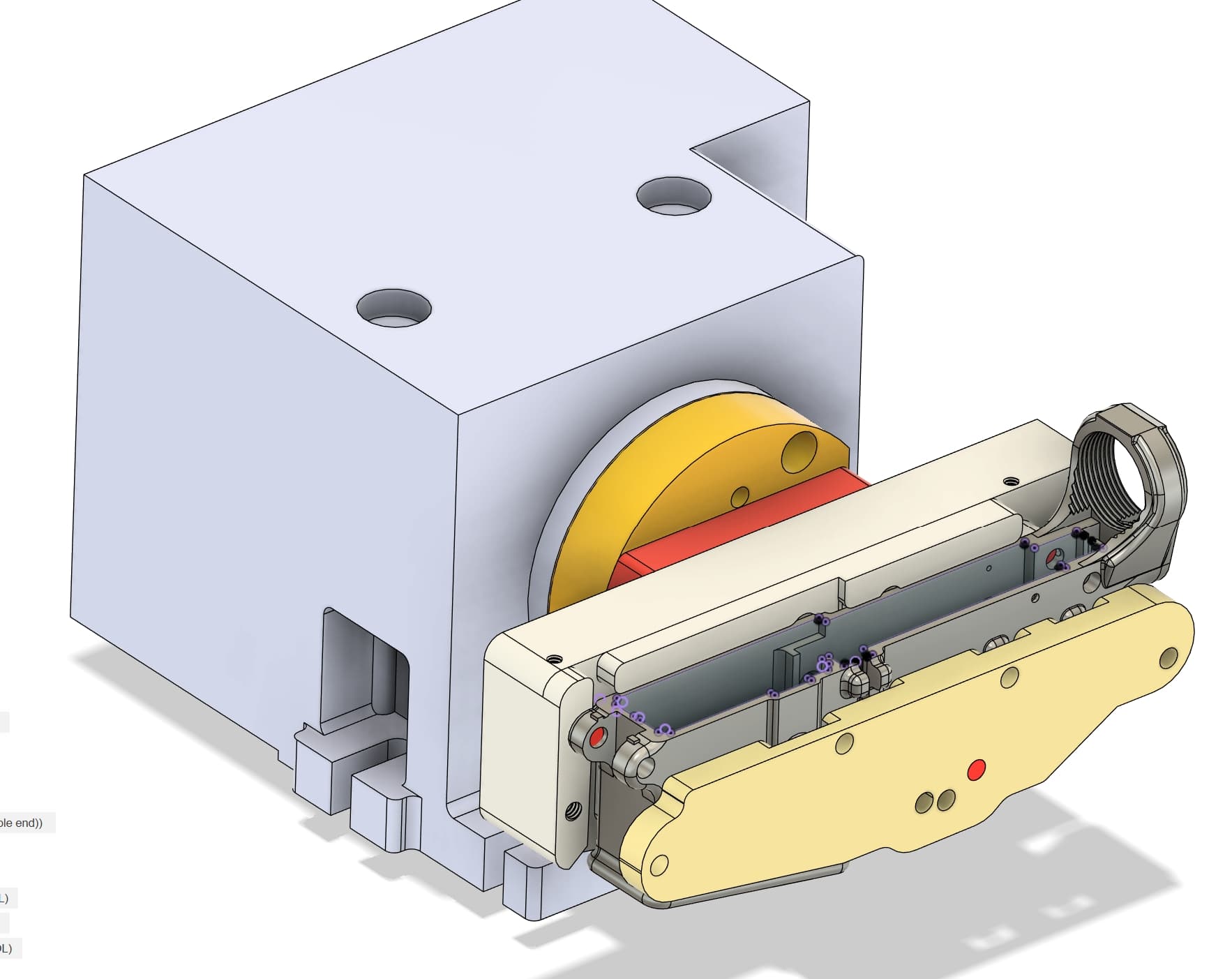
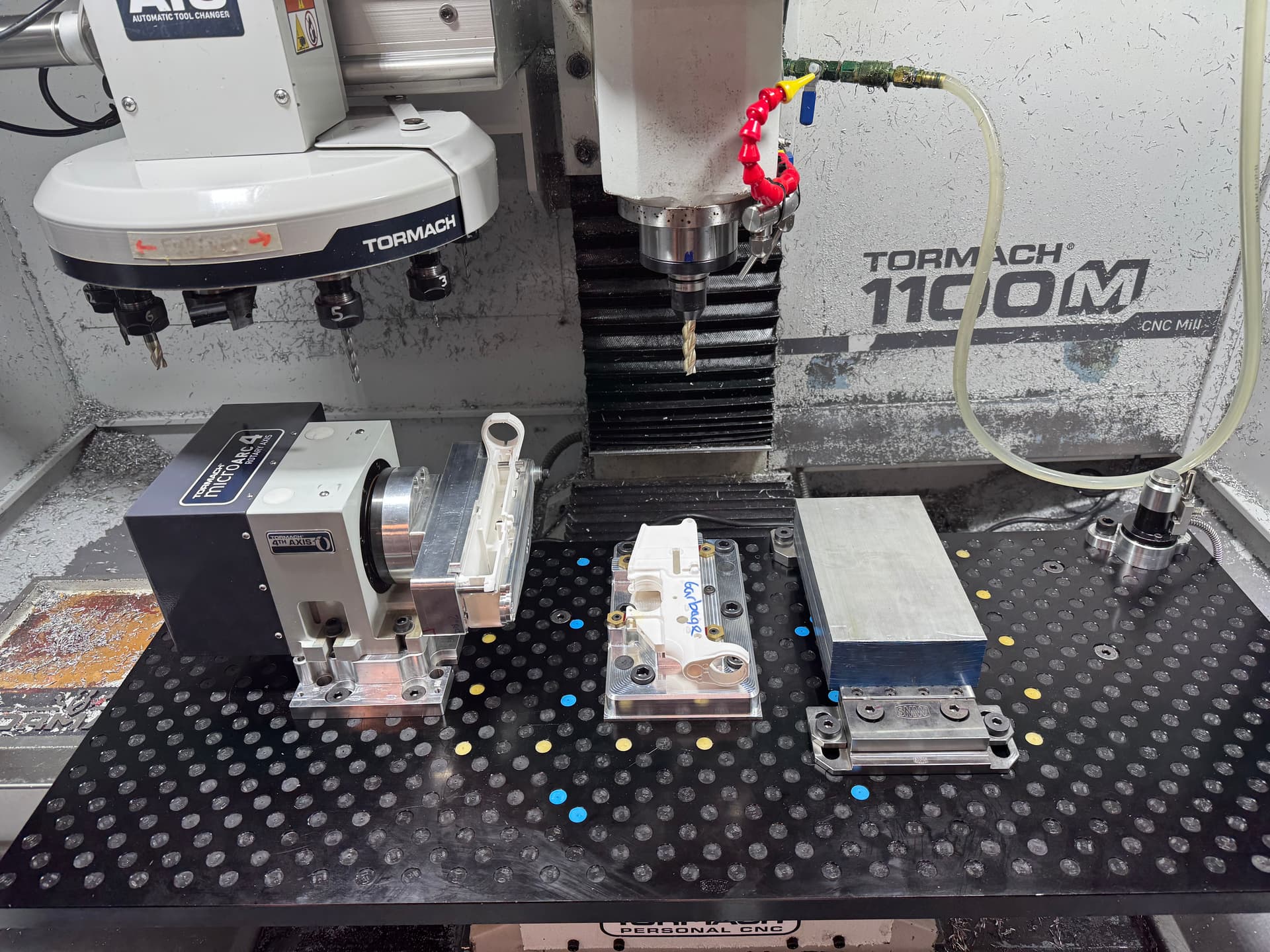
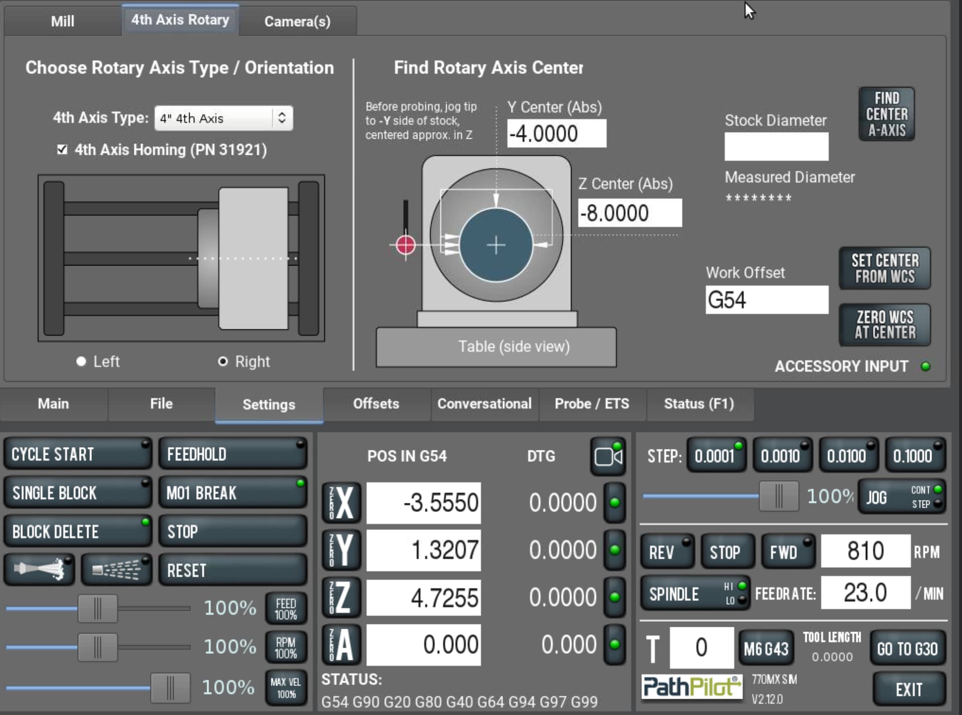
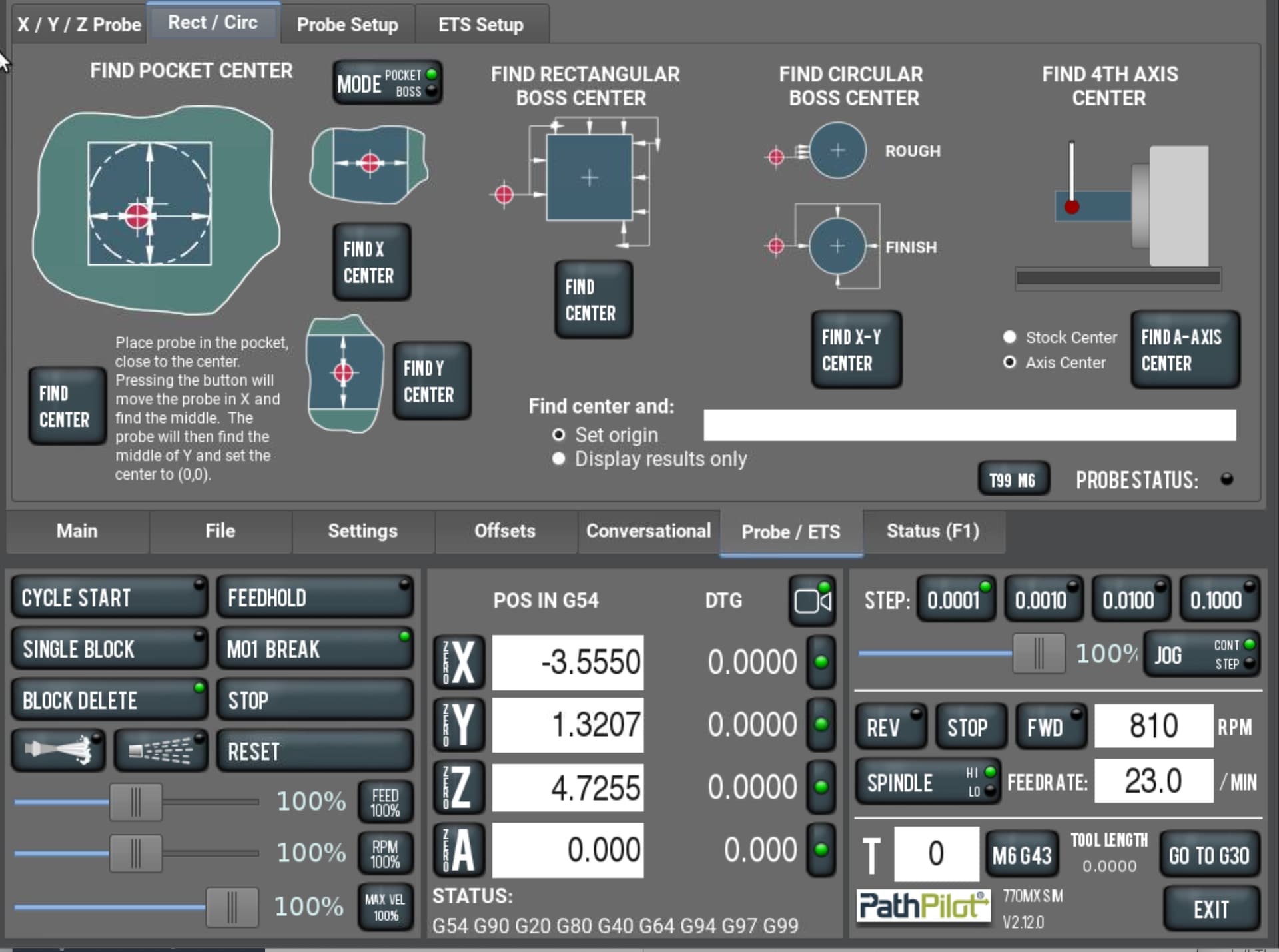
Quick run down Op 1 & 2 are 3 axis, and Op 3 is indexed Micro Arc, Im on an 1100M with a Tormach Passive Probe, doing CAD/CAM in Fusion. I need help with the practical probing setup for my work offsets for the Micro Arc. Ive been thinking about this for weeks, but im not exactly sure how to set up for the 4th axis. And because this is a specialized set up there are no real resources out there I can find as a step-by-step guide. Norm at Tormach has told me just that, and I have not found any videos on indexing. I think its pretty lame there is nothing on this! The part will be indexed on all 4 sides, top, bottom, front, back, plus the angular rotation to drill and tap the hand grip threads. Here’s a picture of everything as well as a screenshot.

Questions.
• How do I establish my starting rotation of the Micro Arc so that my top part face (as seen in my screenshot) is perfectly parallel to the table? HOW do I probe for this?
• Once I get the rotation exactly where I want it do I just hit zero A axis?
• Currently in Fusion, I have my work offset at the center of the Micro Arc in Y&Z with X on the face of the GTM adapter in (part in yellow). I know that when programming for parts that rely on the center of rotation for 4th axis, this would be the typical setup aside from where I have my X. SO, would this be a common OR a standard setup for an indexed part?
• I want to establish my work offsets by probing existing milled faces or features. Im not sure I want to rely on the actual fixture. BUT if you have input on how reliable that would be let me know.
• How would you guys approach setting the work offset for this setup?

Thanks
Bill


I think this page/videos will answer your first 2 questions.

1 Like

First I would probe along that top surface and adjust A until the farthest points from center read 0.0.

Are you going to have to remove the part to flip it?

Thanks,

No once the part is secured into the fixture, it will rotate to the respective orientation (top, bottom, front, back, and hand grip) to complete Op 3.

When you say probe the top surface and adjust A till 0 that makes sense now. I was expecting there would be a probing script like all the standard ones that would do this, but obviously not on the probing page. SO the revelation is that it’s done manually to establish my top surface to the table. Right?

Next question,
IS there a custom probing script out there that can probe a flat surface like this at multiple points and then automatically adjust A rotation to 0 out both ends? THAT would be nice, I have to question WHY this would not be a standard function.

Ill take a look at the video.

Thanks much for the link to David’s video. I have not seen that one. I think it’s going to work out for my needs.

Again its crazy to me that this is not part of the standard Tormach probing. ?

1 Like

Ya it does seem like an obvious probing routine that would be on the probing page. Also a Z&Y probing routine would be great which David has as a .nc file also. Maybe in future releases we will see it, the Microarc or 4th in general isn’t new to Tormach so they must have some reasoning as to why they don’t have that. Maybe the probing guru @nkowalczyk will weigh in on it…

There are probing routines in the latest PathPilot. Not sure when it got added.


1 Like

None of those do what the files discussed above do, unless I’m missing something. This finds the center of round stock to locate the center of rotation. The files above are to get a rectangular part flat or square to the table. The other is used to find Z&Y…

I see. You are correct. I was recently surprised that 4 axis probing was in PathPilot.

Looks like it would be nice to add what those scripts do in PathPilot.

1 Like

I think you may encounter more chatter than you’d like with that setup, at least I did.

Anyway you wouldn’t even need to keep tweaking the A-axis over and over. Measure Z at one end of the flat, move over a set distance and measure the Z of the other end and math. Maybe repeat for good measure in case its way off.

2 Likes

Since I only have a haimer and indicators and don’t have a probe yet, I can’t speak to any of the probing questions directly so I’ll limit my answers to the set up stuff.

To establish your initial level A position, as Harold said, you can touch off the two points furthest in Y from each other and adjust the rotation angle until you see zero on both. Think of it like tramming a vise, only on it’s side. It’s generally a pretty quick process.

Since the machine doesn’t have TCPC, your CAM and therefore your physical WCS should also be set to the center of rotation in Y and Z. I’ve tried not doing this and the results are always bad. That said, you can probe any feature you want to find that centerline as long as you know exactly how far away from center it is. For instance, once you’ve mounted your fixture, first time around, touch one end of it in Y. Then rotate the fixture 180 and touch the same surface (which is now facing the other Y direction). Divide that number in half and you have the exact distance from that face to the center line. Next time you need to locate the Y center, assuming you haven’t removed and reinstalled the fixture, you only need to touch off on that one face, and offset by the previously measured distance.
Similar for Z, once you’ve established the distance from centerline to the top surface of the fixture, touch off on that surface, and offset to center and your done.

As for X, zero can be wherever you want it to be. It has no direct relationship to the rotation center so it can be totally arbitrary.

I get that you want to use the part as your WCS reference, and that is probably the better approach to ensure features are sized and positioned correctly. BUT, bear in mind that if the part moves in the fixture from one cycle to the next, the center of rotation moves relative to the part. So unless you are willing to change the setup in CAM to match, you’re still going to make a bad part. This is the big difference between 3 axis and multi-axis setups. With 3 axis, if the part position changes between runs, the machine still makes the same movements, just in a slightly different position. With 4 axis, if the part position changes, the actual center of rotation does not so if you try to tell the machine that the center is now in a different place, you end up with a mess.

The better approach is to use the fixture as your reference, and make sure the fixture has 3 good surfaces (XYZ) to repeatably locate the part.

I have the newest version of PP and as per Scott Dube It does not do what I need.

I downloaded David’s Loomis scripts and played with it a bit, and then reached out to him as I have several questions on using the scripts to make sure I don’t crash my probe. I’ll post back after I get it figured out. It looks perfect for square and rectangular stock setups.

Not sure why Tormach has not implemented any functionality to facilitate a square or rectangular stock setup for indexing as a standard part of PP probing and setup! Its kind of frustrating! :thinking: Surely I’m not the only one questioning this AND doing this type of setup! I LOVE Tormach support and the mills, but I kinda feel like they dropped the ball on this one, leaving such a complex piece of equipment and setup to our own devices to figure it all out.

Good input, thanks for the explanation on manually doing this. I still think there should be probing functions in PP for this, but this is GOOD because now I’ll know how to do both. I have to question if this is a standard practice for higher-end industrial machines? OR do they have a top dead center type of function??

Years ago, when I was in the toy industry (90s-2000s) as a sculptor, model maker, and prototyper, I CNC-milled all the toys I created in toy sculpting wax. The mill I had back then was a (Roland MDX-650), and it had a 4th axis that would home itself to the exact position with the flats on the jaws parallel to the machine table.

What does this mean?

@Bill_Barschdorf I have the same question about the Y&Z probing routine for David so let us know what you find out. My probe stylus is not long enough to do that routine with the part I was most recently working on. I had to use the method @Ian_Vivero mentions only I use the probe to find the back and front of Y and then divide by 2. Hopefully that helps.

Thanks for the input on this! Ill keep you guys posted, that was one of my questions to David regarding probe length as well.

It might be this…

TCPC 4th Axis Tram

To perform a touch-off and tramming procedure for a 4th axis on a Haas machine using Tool Center Point Control (TCPC), the process involves establishing the machine’s coordinate system relative to the part and the rotary axis. For a 4th axis setup where the part runs left to right along the X-axis, the X0 position is typically defined at the left or right end of the part, while the Y0 position is established by tramming the Y-axis to the part’s surface. The Z0 position, which corresponds to the center of rotation of the 4th axis (e.g., the center of a 1" diameter bar), is determined by touching off the top of the bar at Y0 and then subtracting half the bar’s diameter (0.5" in this case) to reach the center.

When using TCPC, the machine’s control can manage the tool center point relative to the part, simplifying the setup for complex geometries. If probing is used, standard probe routines can be applied, but the Z-axis offset must be adjusted by subtracting half the part diameter to account for the center of rotation. Additionally, if the part has a specific orientation (e.g., a flat face) that needs to be aligned with the A-axis, the A-axis must be set to zero to ensure proper alignment. This setup ensures that the tool path is correctly referenced to the part’s rotational center, enabling accurate machining on the 4th axis

2 Likes

@Bill_Barschdorf thing is, every setup and every use case is different. While I don’t disagree that a square probing routine for 4th axis work could be useful, I don’t know enough about probing on these machines to really comment on it (again, no probe yet). The microarc, and probing, are both “relatively” new features for Tormach so it’s reasonable to think that more evolution will come with time.

A grumpy old man I used to work with would often say to me “I build broken machines and then fix them”. This used to piss me off to no end because, if you know it’s broken, why not just build it right in the first place? It took me years to understand that this was his way of saying, at some point you just have to build the damn thing and then find out what needs fixing, adjusting, improving, etc. Scope creep very quickly leads to a project never actually launching so eventually a decision has to be made that further functionality will be implemented later, so long as the basic requirements are met.

As for higher end machines, yes, some have an absolute zero on their rotaries, but it’s not at all useful for initial setups. Whatever fixture you bolt onto the face plate still has to be indicated in to be parallel/perpindicular to that absolute zero.

And yes, Mike is correct that TCPC is tool center point control. This allows you to program the part with the WCS located wherever you want. The machine still needs to know where it’s center of rotation is but as long as that is set, the part can move all over the place and it doesn’t matter because the machine translates the original WCS to whatever the current rotation is. This has become common on 5 axis machines but is still not the norm for many if not most 4th axis setups.

3 Likes

Try these videos

3 Likes

Thanks, Jerry. These videos are perfect; I had not come across these yet. Funny because all his explanations and confusion are exactly the questions and uncertainty I have/had! Still not sure why Tormach has not put out videos like these for indexing.

1 Like