Hey guys, I’ve been running Op 2s on a bunch of parts. 2nd side is the bottom of the parts so standard hat top removal, adaptive & contour. This is my 1st time doing flipped parts. My Z is perfact and within 5 tenths. BUT The match up from top to bottom on side wall is shockingly not good. Tormach Tech support recommended calibration with, or checking the probe using a ring gauge but did not reference how to do this and I’ve only used the standard calibration method in the set up document.
The match up for theses particular parts is not critical but would be a total bust if these were for a paying customer so I need to get this to acceptable results! So I will ask you guys what type of results are you getting on your machines for flipped parts and what sort of deviation is to be expected? I would expect 1-3 thou?
Anyone know how and what this procedure is? I do have a 1 inch precision ring gauge at the ready.
I can’t comment on your machine’s repeatability when probing, but you can do the ring gauge calibration by going to the Probe Setup page in the Probe /ETS screen. All the way on the right (I believe), there is a section called Calibrate Effextive Diameter for ring gauge calibration. First, enter the ring gauge diameter (1mm). Then jog the probe tip down into the ring gauge, roughly centered. Then verify that your probe works by pressing the tip and seeing if the accessory input or probe LED in pathpilot flashes. Then I think you hit calibrate effective diameter or something in that section and it starts moving in X and Y to probe the inside of the ring gauge. When it’s finished, you can see the effective tip diameter field update to the calibrated diameter. I think the effective tip diameter section of Probe Setup also has step by step instructions, just follow those.
Put a dial indicator on the tip of your probe annd spin it after doing the A+, B+ C+ adjustment. This will tell you if the probe is really centered. I had a replacement probe tip (not renishaw or tormach) where the ball was .12mm off center so even though the tip was centered the stem wasn’t quite centered or vice versa. Either way it ended up throwing everything off for months. Also unless your probe tip alignment is perfectly concentric any rotation from the setup mapping magnifies the error.
Since you mentioned this is your first time doing flipped parts, the first thing that pops into my head is nothing to do with calibrating your probe and everything about how you’re locating your parts. Are you positioning them against a repeatable hardstop and is that hardstop referencing machined features from OP1 to locate X and Y? Or, like many who are just starting out (including me back in the day) are you locating on the hat?
If you’re using the hat, that is almost certainly your issue. If I don’t have the ability to locate off machine features for a second op, I will typically face the hat, since the Z reference at the bottom of the part is easy enough to capture prior to loading the part. Once the hat is removed and the part is exposed, then I’ll touch off X and Y based on machined surfaces.
I redid my probe setup from scratch and went through the entire setup steps yesterday just be make sure everything was set up correctly. This probe is new but was unused for a while sitting in its box. I installed it back in March of this year.
Tip concentricity after probing is. I did not have to make any adjustments.
A 1.7162
B 1.7164
C 1.7162
Run out is .00038 or so, not exactly sure on the 5th decimal place, as my indicator is only a .0005
Effective tip diameter is .1549 I ran this with my ring gauge that is .99998 dia.
I would strongly second Ian’s thought - I would look very carefully at what you are referencing, vs the probe cal. Flipping parts requires very carful thought on your setup, and what you are referencing. To add to his ideas, whenever I am able I machine through features as datums to use on a flip. these features can typically be sacrificial, and only there for the flip before being machined away.
Certainly, your first thought may be correct and it’s all probe cal - either way, best of luck!
Im doing 7 flipped parts all of them are 2 op parts. I ran one yesterday right after redoing all probe sets up steps (see above post on numbers). This part still has the steps on the wall. This has been the worst match up top to bottom yet. BUT my only reference to probe was a .25 hole so I question how reliable that is since the hole is small and the probe tip is pretty large di.
Im on a Kurt DX6 and all parts are located on the back jaw sitting on parallels. All of these parts have drilled OR bored holes though the bottom of the part from .25 to .75. One part only has .25 holes. I am probing the bored holes when ever possible not the hat. I do understand the importance of probing off of only machined surfaces and reliable datums.
I think i got part thickness down figuring out Z.
For my set ups IF I calculate the part thickness and face down to that value I still have more hat thickness left on the part. SO how are you planning and running your 1st ops to make sure you can skim op 2 to exact thickness BUT making sure you remove the entire hat so you can then come in around the part with adaptive and contour to net. I like to leave a good amount of material to hold on to at the bottom to keep the end mills away from the vice jaws, LOL so I’ve left about .2-.25 hat.
Im also working with Sam on this in tech and he is asking me to measure 1 2 3 block and my ring gauge, I’ve never done that and did not know you could use the probing to measure, DAH. How much we realize we don’t know, right. LOL He sent a video.
One thing that helped me was manually probe your part after milling. That will tell you if everything is the same as the drawing. You only need to measure a few heights or corners to get an idea.
Also have you crammed your vice and table?
Also cut a circular pocket and put a gauge pin in it. If you don’t have a gauge pin cut a circle pocket and then cut a circle profile about 5 thousandths smaller to make a pin to fit the hole. If the pin only fits in the hole and can’t be turned you have backlash issues.
Also run the ring gauge calibration and then turn your probe 180. If it’s the same you are locked in. Also zero on the table and then probe a 1,2,3. If the result is t 1,2 or 3 it’s more trouble.
What others said-- I probe the vise setup (usually step-jaws, with the bottom of the step at Z0, back of the step Y0, an X-axis stop and use that as the origin on the flip so it doesn’t need to be re-probed. If your parts don’t have convenient edges for an X-stop, that can be a bit more annoying without doing soft-jaws.
Your vise being out of square is worth checking, if you haven’t already.
When doing multi-op parts I try not to have the 2nd op cut a contour that was started on the first op. I do often contour something that was cut in Op1 and contours are the easiest way to keep you honest. I have had plenty of success with this.
I also leave a hat of around 0.1" on parts less than 2-3" deep (vise jaw opening).
I have SMW fixture plate on the mill and I have a one of a kind SMW prototype sub pallet for my Kurt DX6 both fixture table are trimmed to .0004 tenths.
All my op 1s are finished with a net pass to model. Are you saying you overlaping on the wall or cutting to full depth on op 1? Now that I’m thinking about it it makes sense to leave stock on op 1 then do final contour on op 2 as long as you have a bore to probe. Would that work?
You know I’ve had several people on Practical Machinist say probing the vice is a bad idea BUT a that was the method I was going to try 1st. I thought that was machining 101. Saying there is deflection in the vice jaw. Only thing I don’t like about it is I don’t like probing the top of the parallel becouse of the large diameter ball on the Tormach probe so someone suggested probe the vice bottom and adjust. I don’t have a ruby on my probe.
Good input, today I leaned how to use probing to measure, and I feel so dumb I did not know about this. VERY a cool. This will be a standard practice for me from here on out. What do you mean measure a corner?
See my reply about tramming.
I do have gauge pins up to .5 so will check the bores.
I’ll look api to the other suggestions you mention as well.
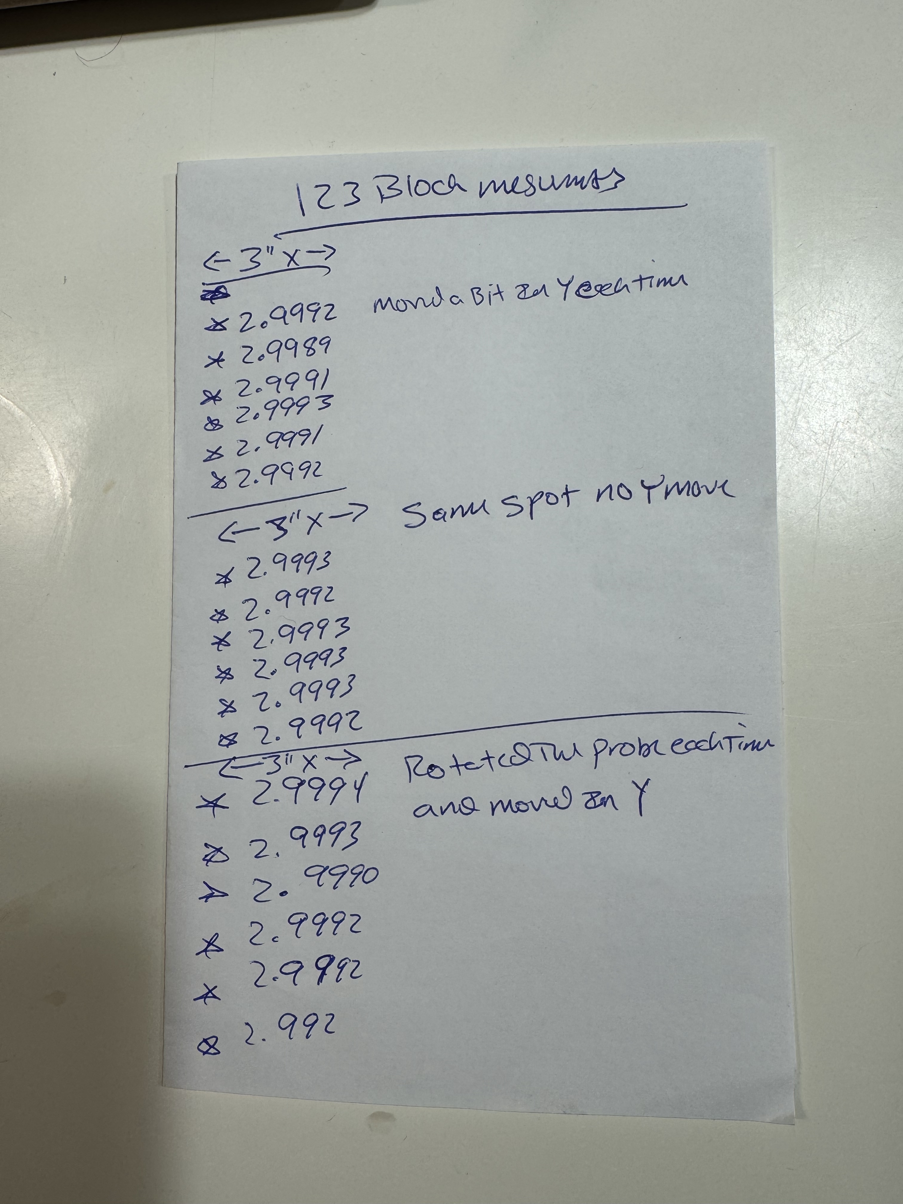
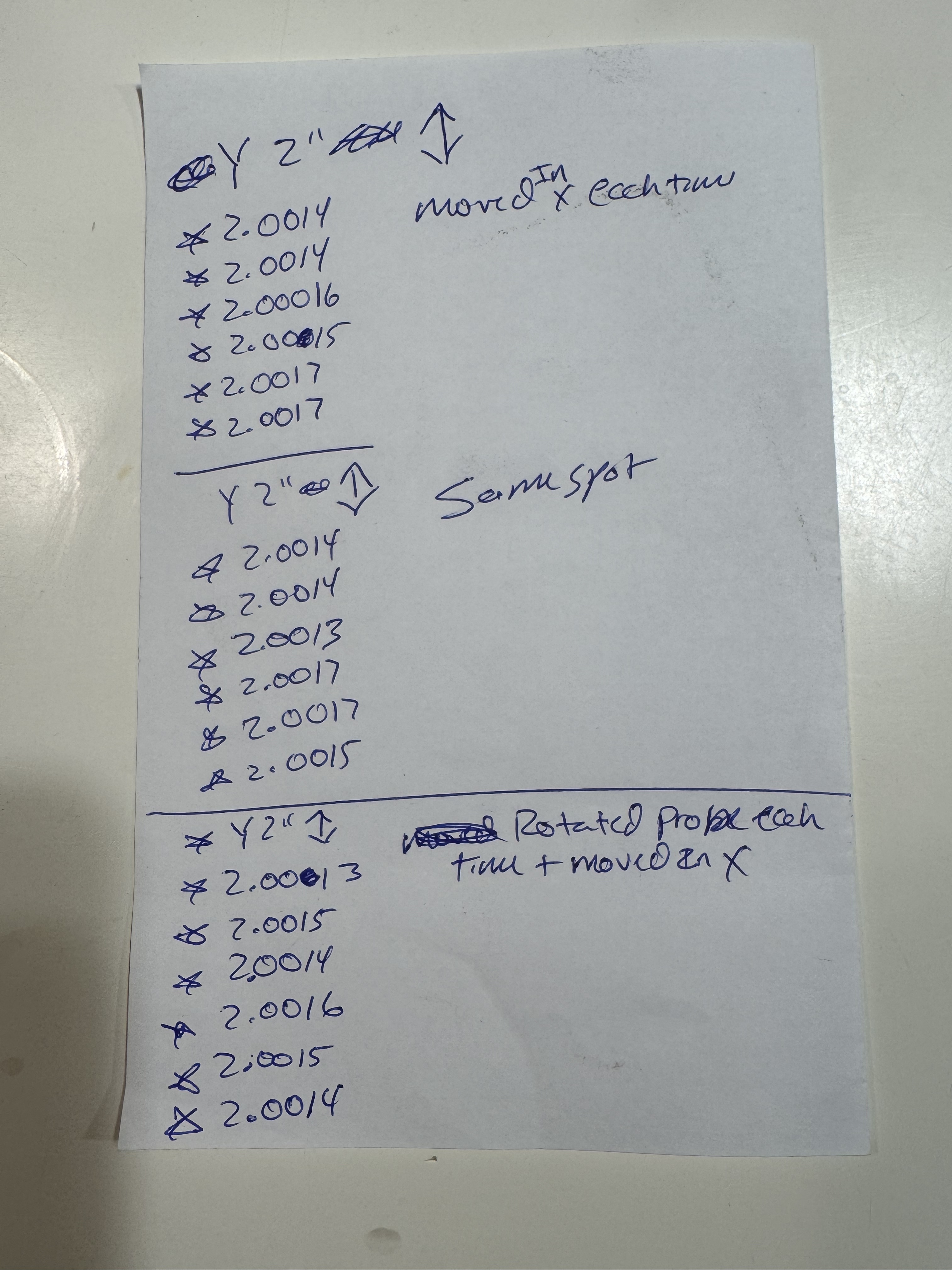
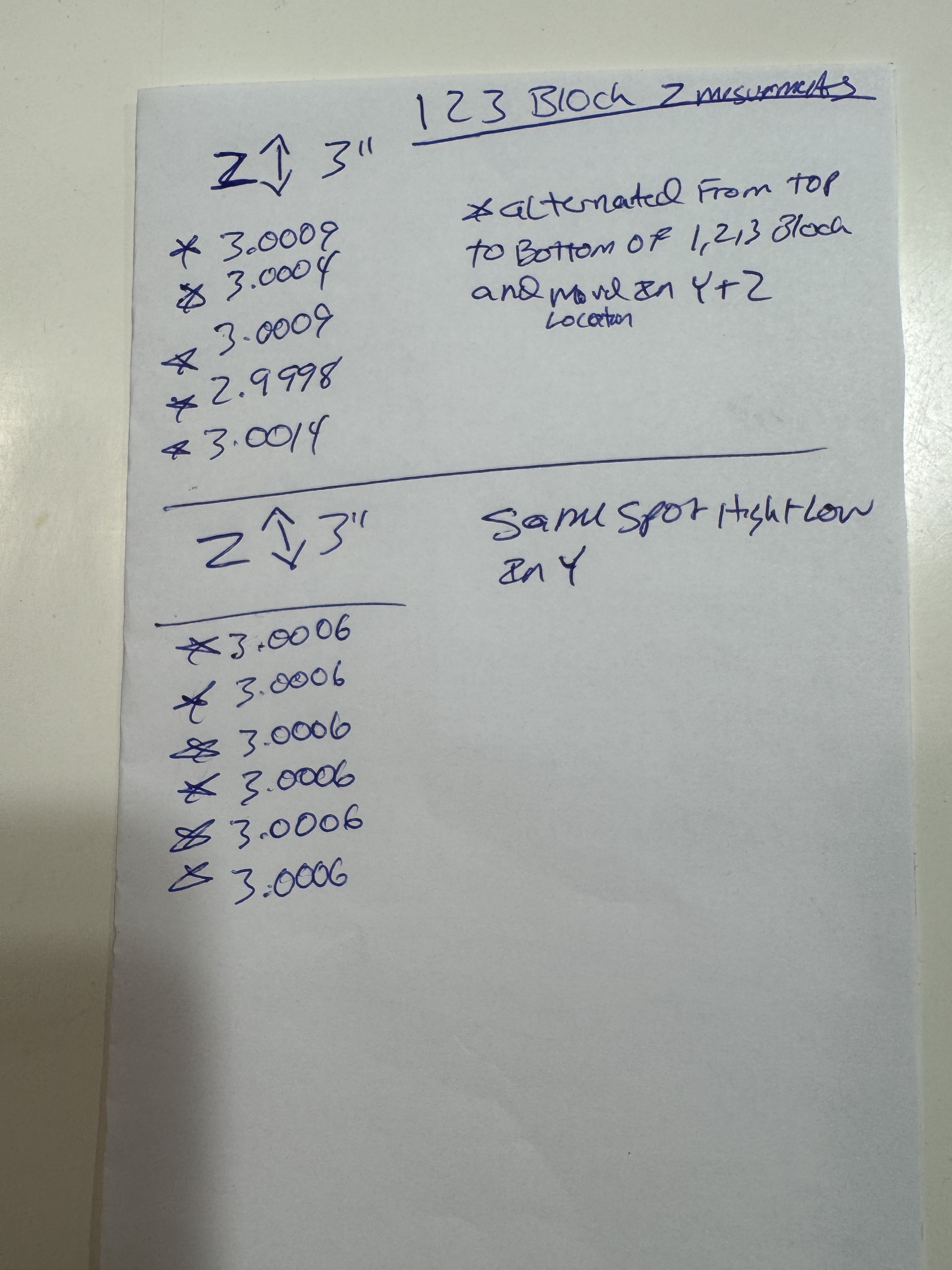
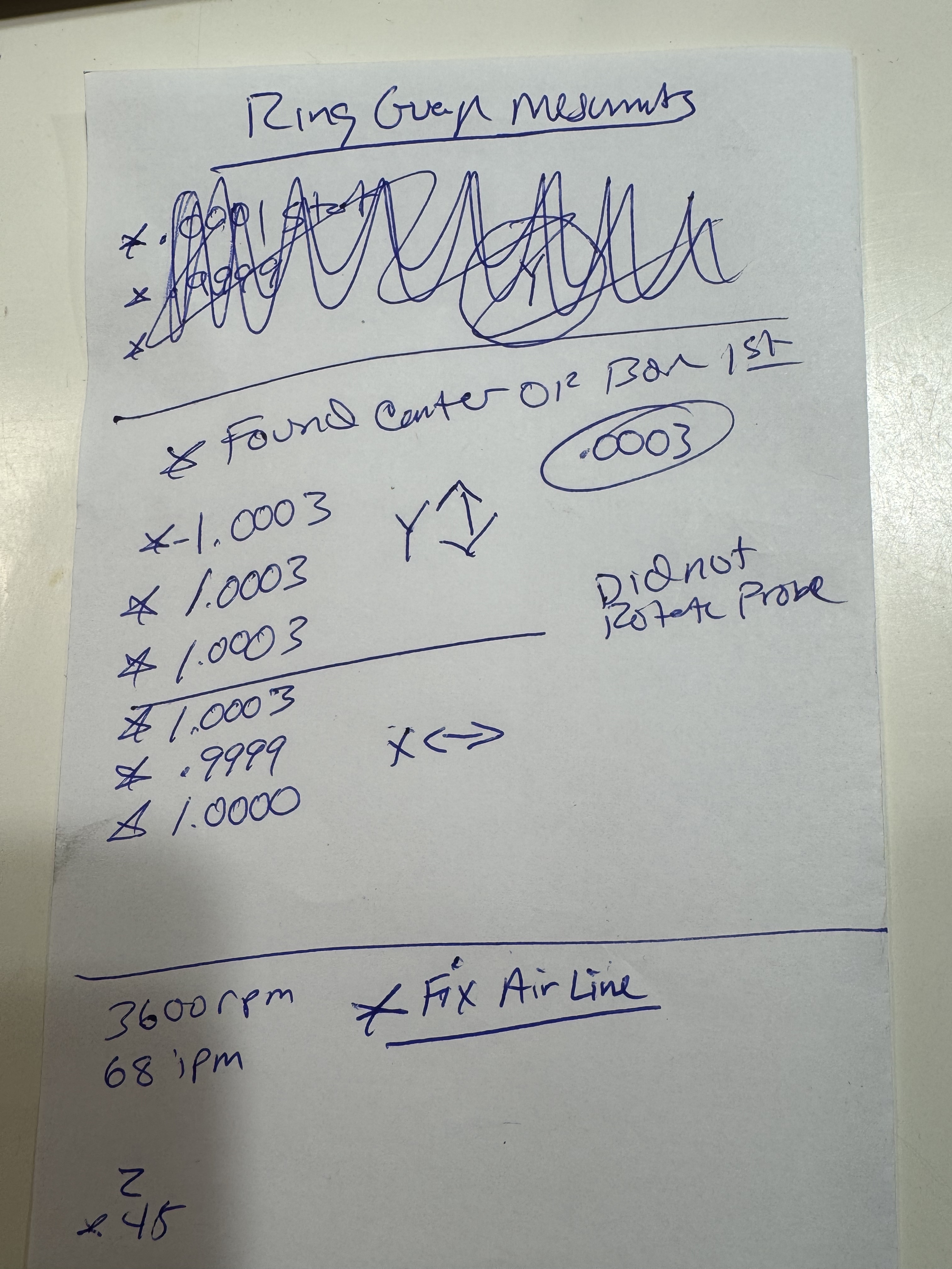
I ran a bunch of measurement tests probing a 1 2 3 bloodied and ring guage. Sorry to bore you guys but here are the results to compare testing you guys might have done in the past. These numbers look good to me, right? Comments?
If you’re worried about the fixed jaw of the vise deflecting (I don’t, there’s lots of other things that I think matter more on our little machines), or if I’m using a thin parallel, then I clamp up a known-thickness thing (gauge block, 123, etc) about the same width as the part, probe it and subtract its thickness to set Z.
On a cosmetic contour if you go full depth on op1 and then a generous chamfer op2, that can cover for some offset as well.
(for anyone that doesn’t have one, master ring gauges in odd sizes can often be found cheaply on eBay. The actual size doesn’t matter for probing as long as it’s somewhat sensible)
If you’re facing to the exact thickness and still have hat left, then you haven’t calculated something properly, or, you’re not profiling to full depth in op1. The hat should be nothing more than waste material that was used to hold the part for op1 OR contain features that can’t be reached in op1. The profile should be cut to full depth.
Assuming you’re trying to continue a profile started in op1, that’s a losing battle unless you’re running a machine that can regularly hold sub tenths tolerances. The slightest variance in position will leave a visible mark and I’ve found even a thousandth off is enough to not only see, but feel the mismatch. At that level of precision, everything matters. Torque on the vise, temperature of the machine and the part, runout in the spindle, error in the probe, etc.
The only time I ever “continue” a profile is when I need to chamfer both sides of it. In that case I use one of two, effectively equivalent approaches depending on my workholding and the part. Either I finish the profile and chamfer in op1 from one side, flip, and chamfer the other knowing there will be areas where it will be off a thou or so, which is not visible in a chamfer. Or, I’ll leave an extra 5-10thou on the entire wall of the profile in op1 but still run the (slightly heavier) chamfer. Then flip for op2, profile and chamfer. That leaves the chance for the op1 chamfer to be slightly off but again, it’s minimal and not typically visible.
I should be complete in my thought process as I realize there are times that the profile simply can’t be finished in a single op. Overhangs that get in the way of parts of the profile, extreme heights that can’t be reached with the available tooling, or other considerations might make it impossible to cut to full depth. In those cases, my best recommendation is to walk in the final pass. Do one or multiple light cuts in op2 leaving a known amount of material behind each time. Check each wall to ensure the expected residual material is actually there and adjust your WCS accordingly. So for example, if the pass is meant to leave 0.010" on a side but you have X- at .008 and X+ at .012, you’re WCS needs to shift .002" towards X+. Adjust, run another pass leaving maybe .005 this time, and check again. You’re still very likely going to have obvious witness marks as our machines simply aren’t capable of the level of precision needed for perfection in this case but you should be able to get close enough to make a good part.
If you measure the middle of a side and then at the corner the measurements should be the same. When it’s not it can indicate loose vice movement or gib problems.
It sounds dumb but you would be surprised how often it shows inconsistencies.
Did you do the casting twist procedure when you installed the machine?
Also have you probed along the z axis to make sure you don’t have any angle on the spindle?
Could you show us a photo of your problem piece after the 2nd op. Also post a photo of your work holding for the second op. I’m starting to think work holding, maybe.