One thing I’ve come to realize with my ZA-6 is that the original table I chose to mount it to for testing and figuring things out is a bit of a source of error because the table top flexes somewhat and in general, the table is not terribly rigid. Fine to get started, but I realize for accuracy, there’s probably a better way.
Just wanted to start a thread to see what the current thinking is, and what folks have had success with and what some Tormach-recommended options are for mounting the machine?
I’ll start by saying I’m currently weighing the tradeoff between the flexibility of having it on a table, vs. the rigidity of some sort of pedestal or floor-bolted fixture from an accuracy perspective. My table has been good, but if it shifts even a mm or two from vibrations and motion/momentum, things start to go bad pretty quickly.
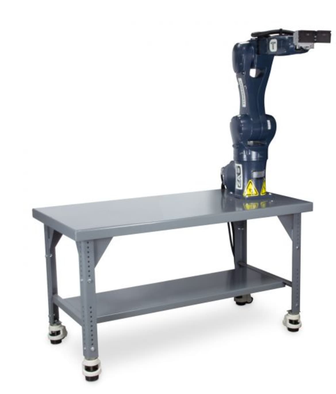
Our current product offering to customers is a 30"x60" steel workbench. The top is 7 gauge with a 2" flange bend around the perimeter. It’s a low-cost, off-the-shelf, simple solution:
When we do QC and mastering we use a base that’s considerably more substantial. I’ll post a photo shortly, but it’s essentially a thick wall round tube welded to two square 1/2" thick flanges. We anchor it to the concrete floor. The QC procedure runs the robot at higher speeds than customers currently see, and with much higher accelerations. It allows us to take data on effort required to move each joint which helps spot a problem, for example, with a bad harmonic drive.
In general, if you are after speed or high repeatability, you want high stiffness and you want to anchor your table to the floor so the table can’t ‘walk’ away from your work area.
I mounted the robot to a 1.5” thick maple workebench and added fold out leaves that extend to the edge of the robots work envelope. All surfaces were then laminated with whiteboard material. This setup will be used in a school setting.
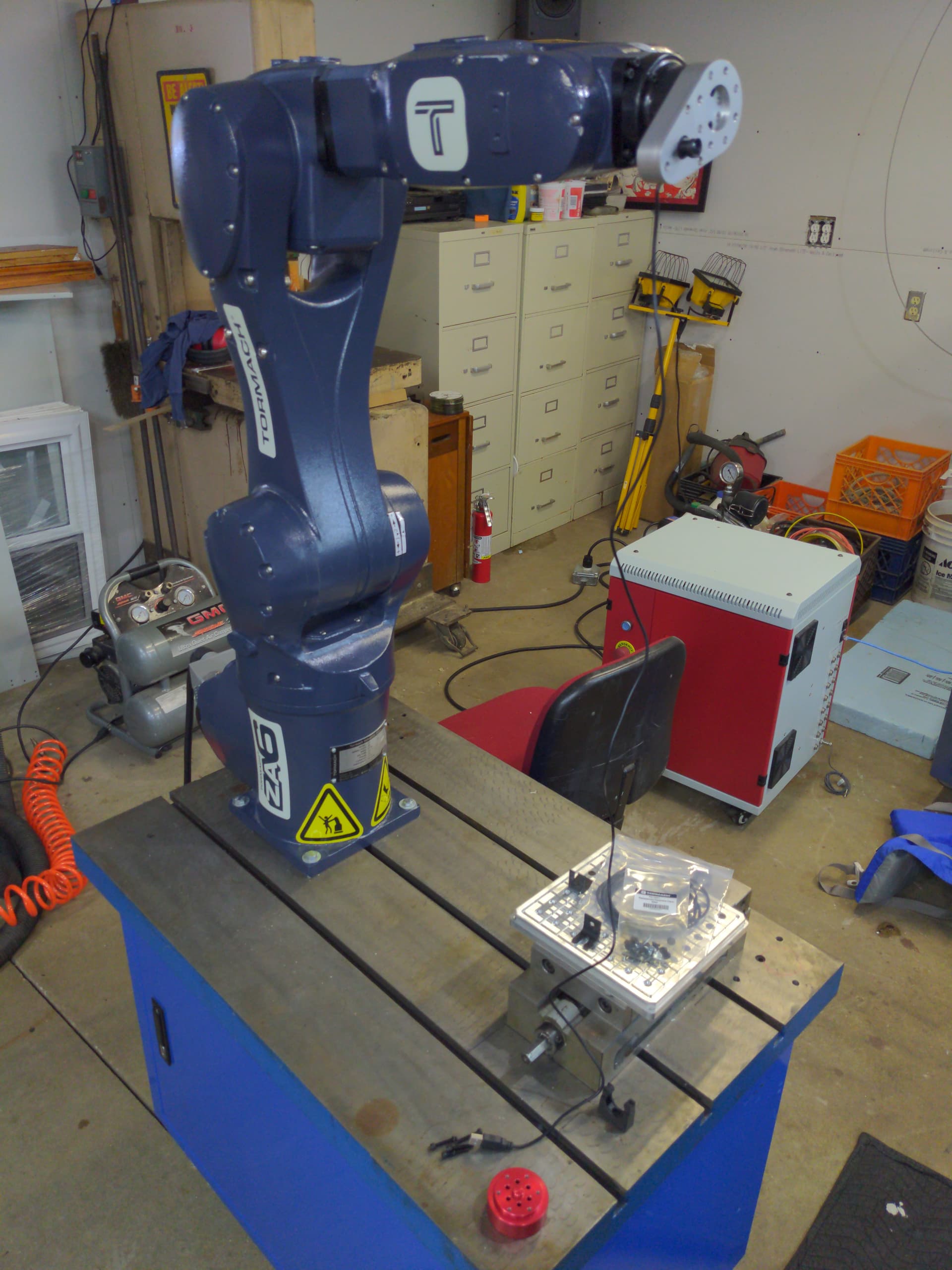
I like that cast Iron base. Those tee slots are going to come in very handy. I thought it was a stand from a scrapped radial arm drill, upon rereading i see its from a tap table…thats OK…I still luv it…
@bigtchopshop Any chance you have a tool path available for one of your problematic movements that was resulting in a placement shift? I know I am way late to this party but am doing some motion/table/mounting testing and am curious in a real world scenario to test against. Thanks.
Not per se. My use case scenario is largely machine tending, and if I make a mistake, then I’ll often have a bump or a torque when I’m placing parts or jaws onto the machine table. Basically, in that case, the machine doesn’t move, so if the robot bumps it, then the robot/table moves, so when I reset the fault and come back in, I may be 1mm off or something, and that causes the grief.
So, I’d say, my motion is fine as long as there are no impacts, but a bump or something will translate back and shift my robot table over and then it’s time to re-train all my positions…
Probably not as heavy as it needs to be. haha. It’s a large ULine packing table with the steel legs and whatnot. I’d say it clocks in at maybe 150 lbs. I clamped it to the CNC machine as well to keep it from moving, but on a bump, it can shift enough that all my alignments on pick up points and such are lost.