I have been working on this project and tried originally machining it in a using a combination of horizontal and vertical orientation sand ran into a number of issues with OP3 not registering properly because of the part was not perfectly symmetrical.
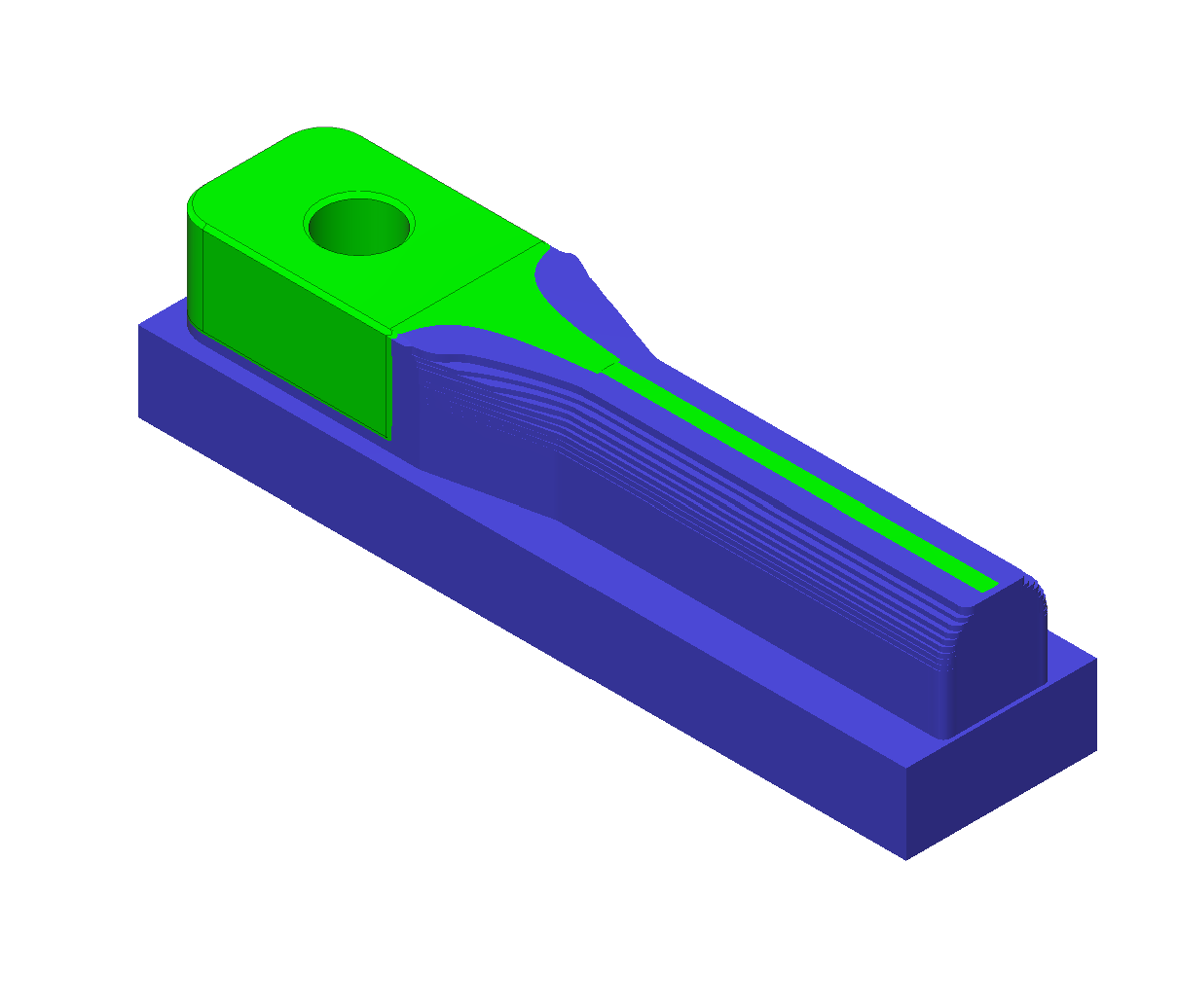
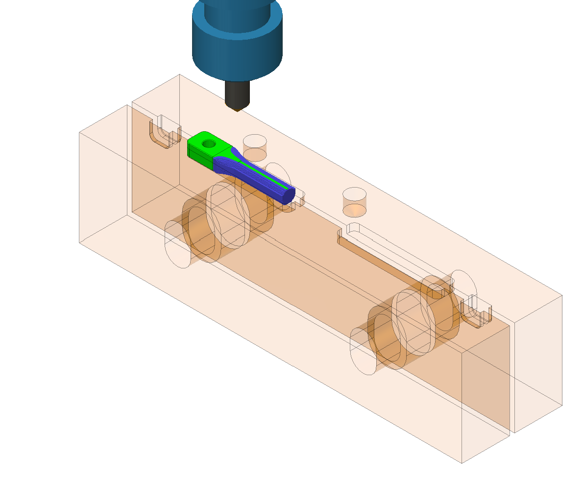
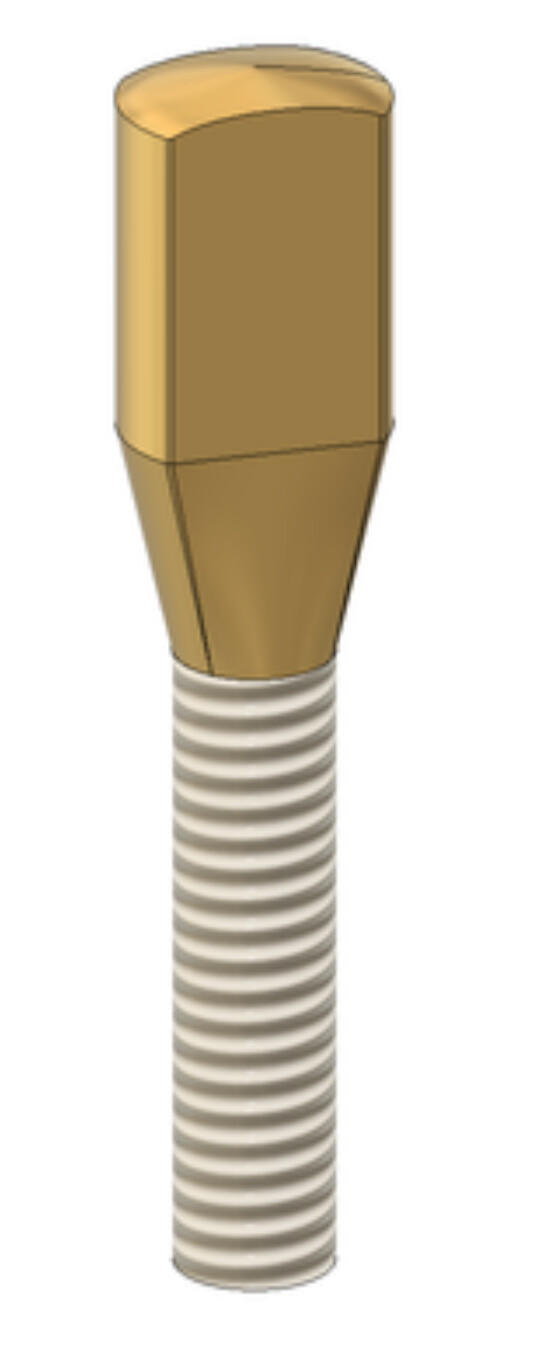
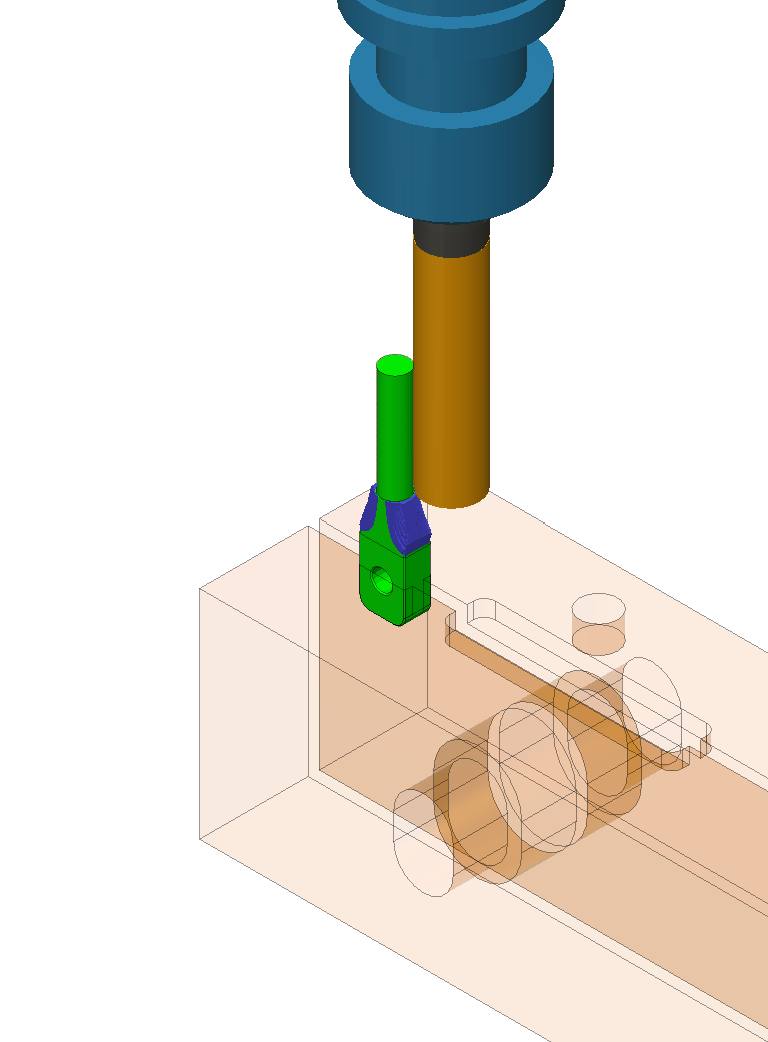
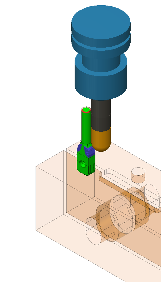
I would like to try a different approach with the difficult features machined ALL in the vertical orientation, I have modified the part a bit. The stock would extend well below the part for setup1. Basic order of operations:
Setup1:
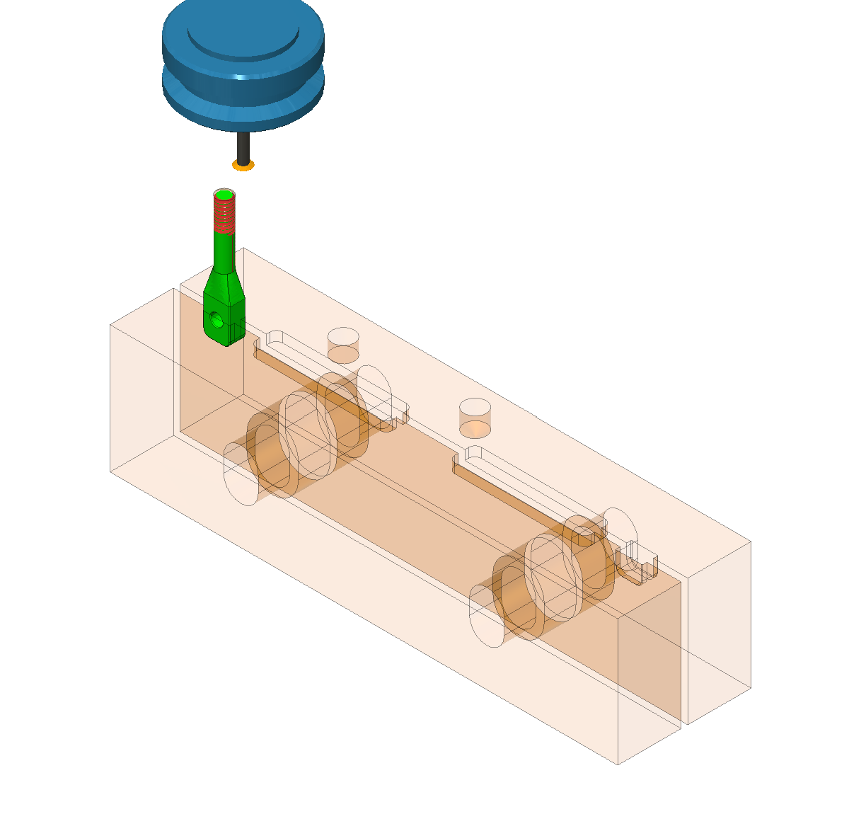
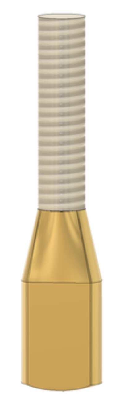
Machine threads, leave all stock below threads for rigidity while cutting threads.
Use ball nose to machine area below threads as in past approach.
Flip part and thread fully into 1/4-20 threaded female fixture until threads bottom out (I will modify the part to have a small flat at the bottom of the threads).
Face excess stock and leave .020" above the model.
Use Ball end mill to machine curvature (dome shape) on top of part.
For Setup2, will threading the part into a female 1/4-20 thread work this kind of work holding? I have never tried this before.
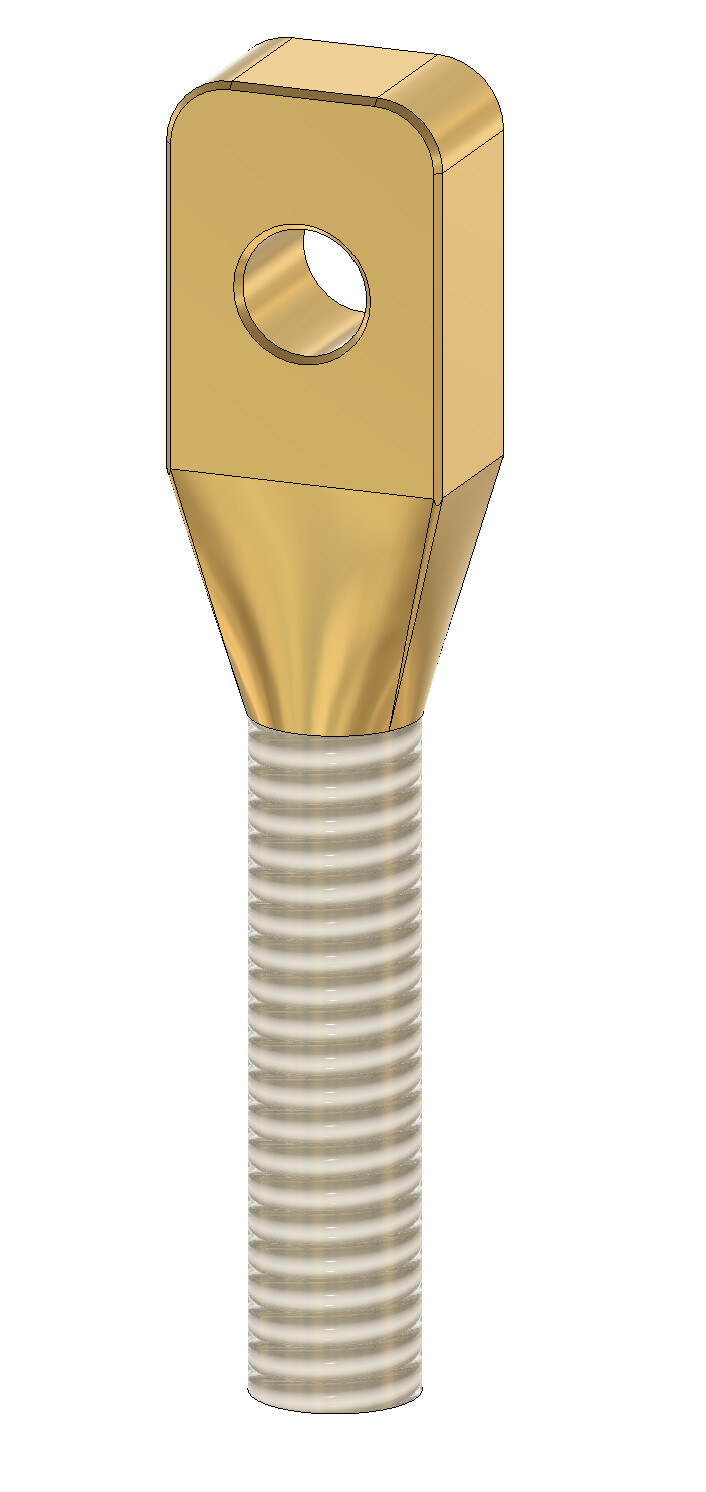
As just finished writing this post, I realize with this revised part shape, it no longer lends itself to drilling the hole in it after setup2. Back to the drawing board
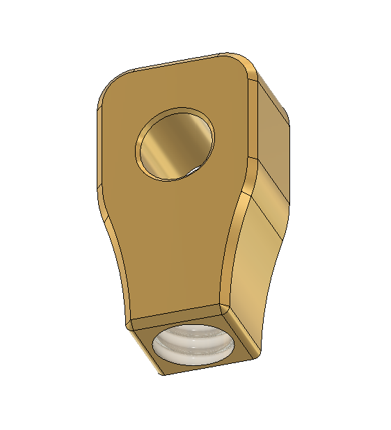
Any suggestions as to a better way to make this thing? Here is the original shape of the part I tried for attempt 1:
It’s very easy to ‘unscrew’ threads with cutter torque (so avoid ‘ticking’ hold down screws too), so you’d want some sort of alternative hold-down or cutters that will work in reverse which would tend to tighten it. Do you have a lathe? This looks like a lathe part.
Yes, lathe. Just drill then face and into the lathe
You will never be able to keep it from unscrewing while machining. I tried what you are trying once and even tried screwing it in and welding the bottom and it snapped at the weld and unscrewed. Also each time the part unscrews it snaps the end mill. I also tried puting a slot in the bottom and puting a pin in to hold it. It almost worked but the slot starts to open up and it gets sloppy.
I think this is some kind of medical device so it has to be exact. I would clamp the whole bar horizontal drill the hole, then run a form mill around the top and face the z+. Then flip it and face the other side. Then clamp vertically and threadmill. <= This clamping is going to be problematic.
If you had a 4th axis this would be a lot easier. You could just thread the bar and screw it into the A and form mill and face and be done.
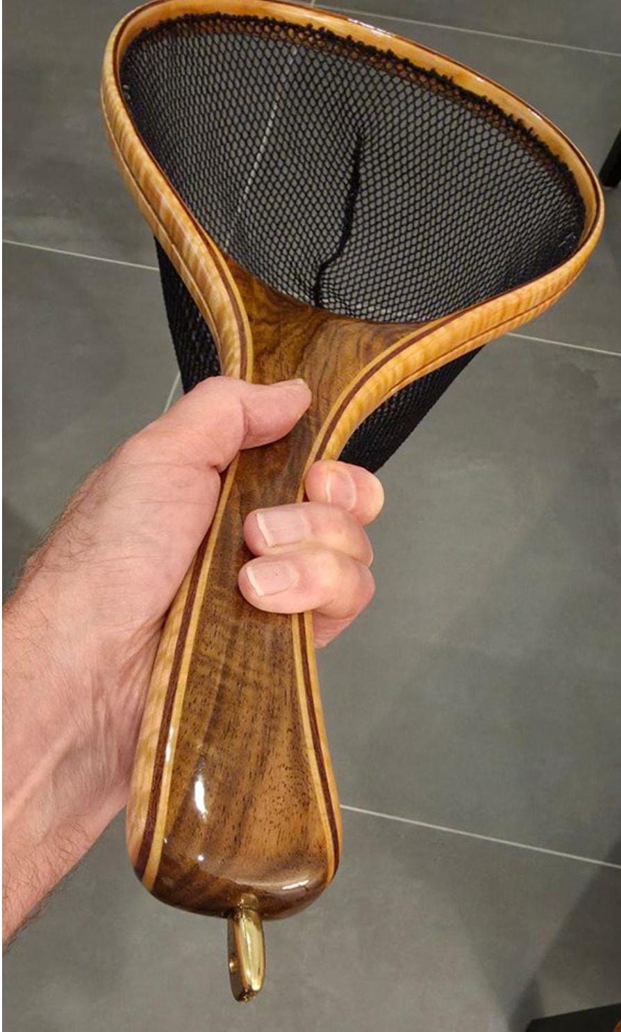
Thanks guys, I appreciate your thoughts. I do have a small, very basic lathe but I was trying to make this part on the mill. It is actually just a small piece that gets screwed into the end of custom fly-fishing nets that my brother makes.
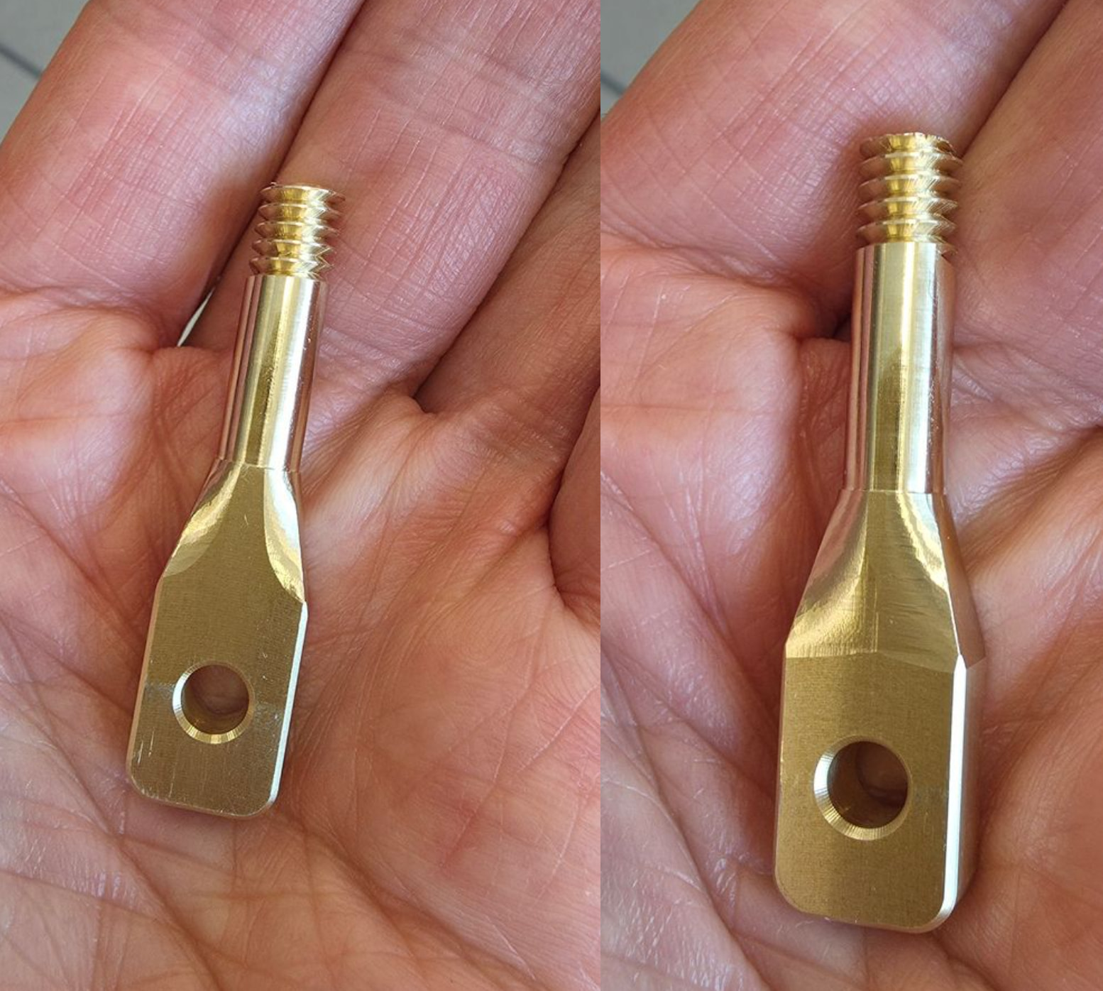
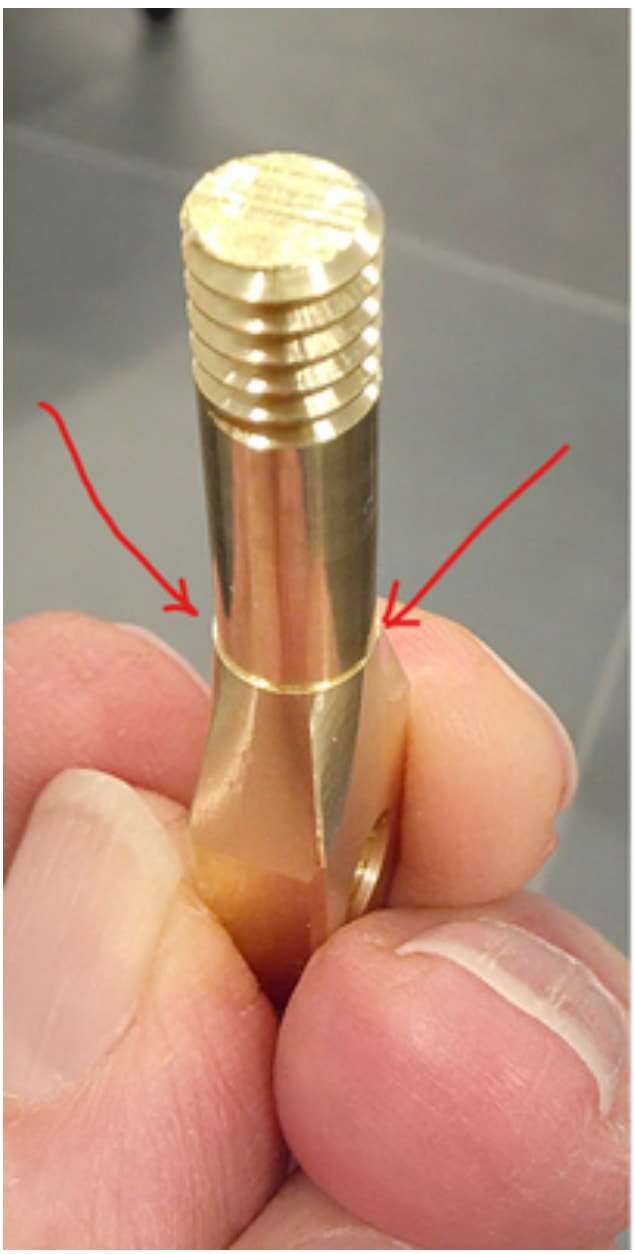
I thought I designed something I could make for him easily… but no luck. One or two came out great, and the others off center for some mysterious reason. The images below show the front and rear of one test piece. Looking at the section that was machined with a ball nose, it looks like the part was machined off center in OP3, but looking at the shaft section above it (where errors are amplified), it looks perfectly concentric.
I cannot decide if I want to try to run it again, or simply come up with a more machine friendly part. Leaning towards coming up with a mill friendly design. If you have any suggestions as to how to make something that is similar and easier to mill, I welcome your thoughts.
Here is the file of the part that I have attempted to run if you are interested. One interesting note is that the part is supposed to be .25” thick after OP2. I found them to be within .0005” which is not enough to create this kind of error.
One other note, the last time I ran this, I actually used hard jaws for both OP1 and OP2 and had the same problem.
Two methods I’ve used for clamping on threads: 1. bore/threadmill into soft jaws, 2: turn a cylinder with threads, split it along it’s length, clamp the cylinder, crushing the slit down.
“For Setup2, will threading the part into a female 1/4-20 thread work this kind of work holding? I have never tried this before.”
This likely isn’t a help here, for this problem, but I have done this. In a lathe. I did this by cutting the threads first then threading that into a trapped piece in the chuck. This worked because the cutting forces were always tightening the threads.
Problem with the mill is it’s always unscrewing the threads. Unless you can find some reverse end mills. I’m sure someone makes them but I have never seen one.
Thanks again for all your thoughts. This project has been bugging me because the fact that the “shaft” section appears concentric, but the curved section machined by the ball nose is off by quite a bit is puzzling.
Thinking about all your thoughts regarding work holding may have given me the clue to what is happening. The shaft section is machined first and at this time the part is help in place. The curved section machined with the ball nose is machined afterwards and the force of the ball end mill has moved the part. I clamped it in the vise with 25 ft-lbs of force. Does this make sense at all?
Norman, your idea of holding a threaded part sounds interesting… Do you happen to have any images of this… a bit hard to imagine.
PS: I have considered machining this as two pieces as was suggested. The one-piece design just looks better.
The thing about threading is that there is always play in the threads so even if you hold it that way the part won’t be exactly where you think it is. That tiny shoulder looked fine to me. Especially since this isn’t medical equipment. Since it’s brass You could always grind down that little ridge and polish it back to perfection.