I would like to use the drill chuck on the 8L lathe but I can’t find any information to guide me. I’m not sure how to override the door.
On the 15L you just lift off the slide down cover on the right side of the machine. That gives you access to the tail stock quill handle.
Yeah, that would make sense. The 8L does not have the panel and there is no reference to using the quill handle in the manual or videos.
I purchased an mt3 toolhoder for mine because the tailstock took up too much space and the turret only hold .75 size tools. It sucks to use an indicator to set the height and x position. Once it is set though you can drill to any depth with g code and use a peck cycle.
The 8l has interlock switches that disallow you from operating the tail-stock while the enclosure is open. If, however, you want to pursue this, the tail-stock has an MT2 taper.
Since you can’t drill a hole in the “traditional” way we recently added the ER20 MT2 tool holder to the 0XA Tool Holder Kit and should have the 51666 - ER20 collet chuck with MT2 taper shank up on the web pretty soon. The MT2 0XA tool holder will also give you some options for holding drill bits and such.
1 Like
So would I be correct in thinking the tail stock on this sort of lathe is ONLY for workholding (i.e. supporting the work on a centre). The only reason I ask is I am just wondering the simplest way you might wish to cut a support ‘hole’ for a revolving centre. I might consider using a centre drill in a chuck in the tailstock, thereby being sure the hole is aligned with the tailstock, and also saving having to figure out how to program the operation. It could be done in 2 minutes flat!
I made 2 small plastic pucks about 1" in diameter with a magnet embedded in them. I use those to bypass both safety interlocks on both doors. I then made a plastic shield that extends out about 10 inches from spindle that is held in place with magnets. to contain coolant and chips. Now run my lathe with the doors open most all the time. I am handicapped and found opening and closing the doors would wear me out after an hour or 2. Also my lathe has a problem with the motor housing door interlock. It will often get confused after opening the door and will not allow the lathe to restart. A complete power down for 30 minutes is required before I could use the machine again. Bypassing the door interlock fixed this problem and I no longer have to power down to fix it. Anyway, having open doors saves me a bunch of movements and effort. Also, provides complete access to the tail stock for any need i might have including drilling center holes or deep holes, adjust coolant outlets, pull bird nests of chips out. ![]() I know Tormach would not advise this, and it could be a safety issue. I have a manual lathe and it has no cover and is used the same way. Just need to be safe with hands and clothing around all the tools in the shop.
I know Tormach would not advise this, and it could be a safety issue. I have a manual lathe and it has no cover and is used the same way. Just need to be safe with hands and clothing around all the tools in the shop.
hope this helps.
1 Like
Okay, thank you. I did see the extra chuck. I am using these in my manual machining class and I was trying to teach it like my manual lathes. I was using my tailstock with a live center and thought the drill chuck in the tailstock was the easiest method. It may be better to just have the students prep the workpiece in the manual lathes before bringing it to the 8L.
Yes, this was my original plan. My student’s end project is a machinist’s hammer and I thought they could complete the tapered handle in the 8L. I may just have them prep the piece in the manual lathes.
I like the workaround! I think I have to keep the doors in place since this is a classroom setting, even though I have 10 manual lathes with no doors.
I use a drill chuck in the tail stock and the 8L like a manual lathe all the time. The sensor that detects when the door is closed is a simple proximity sensor that detects the presence of metal. I have a small piece of metal that i set in front of the sensor when I want to keep the door up. Just remember to remove the metal target before closing the door again.
2 Likes
To be clear I didn’t remove doors. I just have them open most of the time and use a 10-inch-wide custom shield to control coolant and chips. I do this to save a lot of movements opening and closing the doors all day.
Did your machine come with a tailstock? I have a 15L and would like to have a tailstock, but have not been able to find one.
The 15L tailstock was discontinued quite some time ago. Only the 8L has a tailstock option.
I purchased the tailstock when I originally ordered the machine. I had it in the machine for a short time. It takes up a substantial amount of space inside the machine.
Did you have any issues working around it, I’m curious because it is one of the things, I hear a lot of people ask for but not sure if the machine would function well with it in place. Specifically, does it restrict from turret or part length?
Thank you in advance, I will use whatever feedback you provide to help others on other forums too.
I will pull it out of its box and place it back in the machine and post some pics. It’s been so long Ido not remember the issues and I am not interested in making anything up.
I have been using Lane’s solution to be able to defeat the Enclosure Door Interlock since I received my 8L lathe early last fall, but I wanted a more permanent solution so that I do not have to remember to remove the 5/8” Lathe Tool Blank which I have been using to close the interlock circuit. I have slightly bent the Enclosure Door twice when I forgot to remove the Lathe Tool Blank when closing the door.
I wanted a physical switch which I could flip when I needed to use the Tailstock with a Drill Chuck. The Proximity Sensor is a NPN device, so a simple contact closure would not work, so I made a parallel circuit which uses an NPN Transistor when the switch is flipped.
The original circuit for the sensor is shown below.

I cut the Sensor lead about halfway between the sensor and the terminal block (inside the wire race) and patched in a 6 conductor rainbow cable over to the end panel next to the Accessory inputs. (I used brown, black, blue for the wires to the terminal block and white, grey, purple for the sensor leads) This cable was run inside the wire races and the patches were covered with heat shrink tubing. The wires to the terminal block (#400, #401 and #413) were soldered to the center contacts of a 3-pole double throw switch while the three wires to the sensor were soldered to the three contacts which make contact when the switch is in the up position making an identical circuit to the original.
The following circuit shows the addition of two resistors and a NPN transistor which were soldered to the three poles of the down position switch:
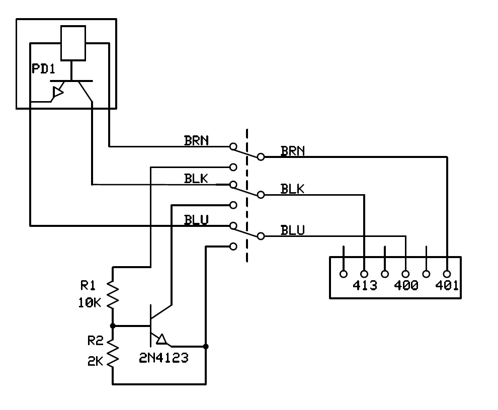
The two resistors (10K and 2K Ohms) provide 4 volts to the base of the 2N4123 transistor while the collector of the transistor is soldered directly to the ‘Black’ lead on the switch. This circuit is only active when the switch is in the down position.
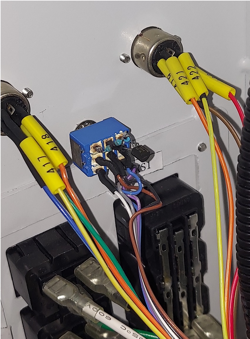
The following shows the switch mounted near the accessory inputs with the two resistors (blue) and the transistor on the top row of contacts of the switch:

If you decide to copy this design, make sure that you get the resistors in the correct position since the higher voltage will ‘cook’ the transistor if you get them backwards. In addition, flipping the switch when the Spindle is turning will usually cause the Spindle to stop since there is a ‘dead’ spot in all switches which do not make a connection with either side in the middle of the switching process.
1 Like