I am ready to check the tram for the table, and it appears my table is not square. I’m not sure the right way to make sure it is level left to right and front to back. The owner’s guide doesn’t have anything that I could find other than section 11.4.6 “Adjust the Geometry of Precision Mating Surfaces”, but it doesn’t have any helpful information on what and where to shim, if that’s actually my problem. Can anyone point me to any detailed guidance on this?
You should follow the leveling the mill instructions.
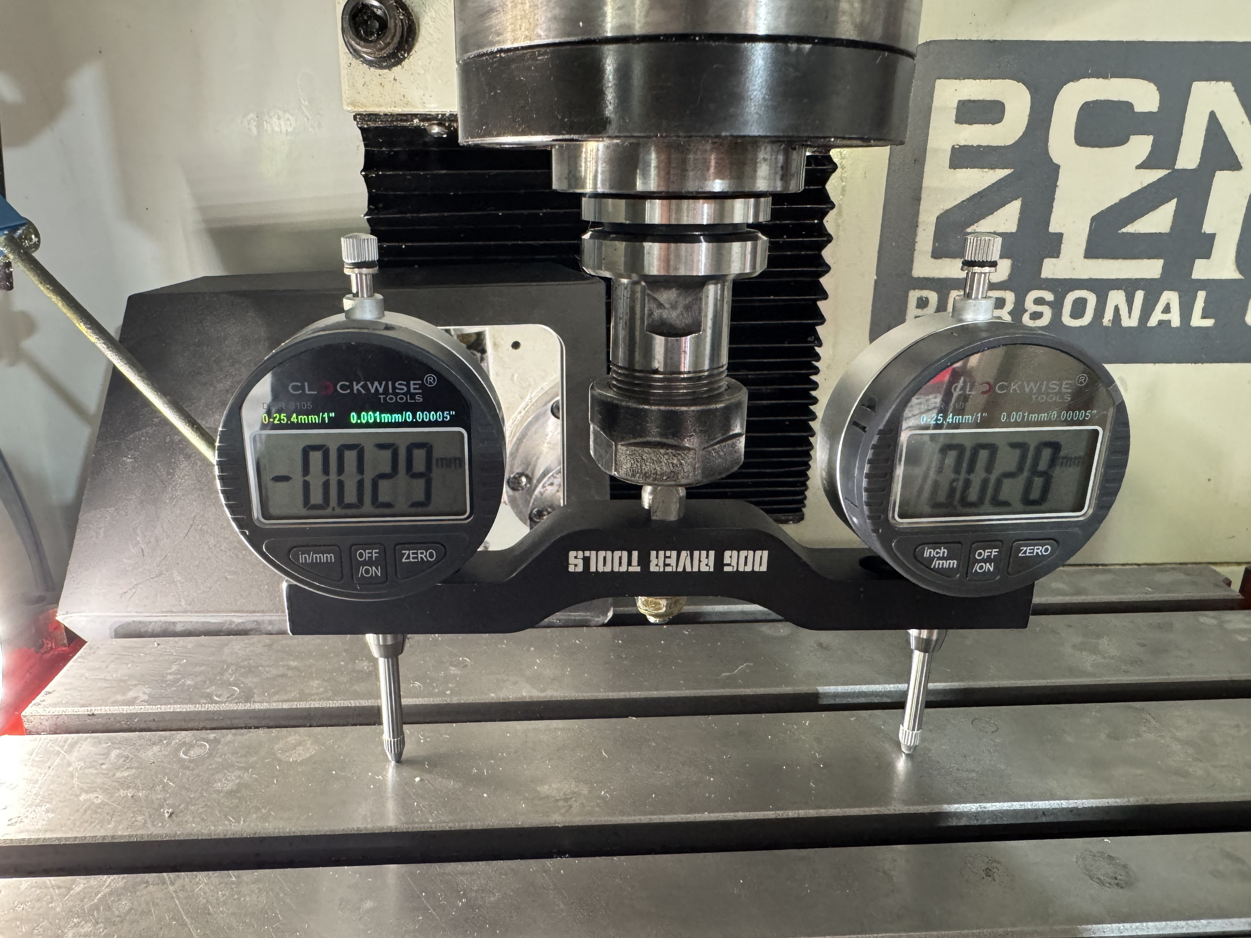
Also be aware that because of the accuracy of the gauges, 0.001 on the left and -0.001 on the right are basically the same. Dial gauges are only accurate to .002 +/- .002. Usually, unless they cost 3 grand each.
Spin the whole thing 180 and break out the mirror. If they read opposite your table is out of level, if it’s different than the 0 degree reading the bars aren’t square. Do the same at 90 and 270 degrees.
Whats the floor situation? Is it industrial building foundation, or garage floor. How accurate is your machinists level. A $300 engineers level is a good start to get close to 0.009. To get close to 0.003 you probably need to get a 10 arc second level, about $2,000.
But the solution to your dilemma is most easily found by asking, What are you making?
Unless it’s space craft or optics, you probably don’t need to get closer than 0.01mm
Also if this is a new machine it’s going to change a lot over the first hundred hours so don’t go too crazy now. Let it wear in a little and then get nuts on the tolerances.
Also stone your table and do an average measurement. The better you get to know those dial gauges. Label each one so you can tell them apart and get to know each one.
I have about a hundred posts about squaring my table and it’s a never ending story.
Thank you for the reply. This is a 2017 machine and is in my garage on a not quite level concrete slab. I did work on leveling it with a machinist’s level over the weekend prior to this. It’s not perfect, but it’s very close. I used a cheap Amazon special that is listed as an 8" Precision level with accuracy at 0.0002" over 10". Since I’m not planning to do anything with tight tolerances, I’m not worrying about the expensive setup. That may be something down the road, but not for now.
As far as spinning it around, both sides read 0 on the other side. I didn’t think about the bars not being square. I’ll have to test the trueness of the spindle and see if it’s the bar/holder or something with the spindle. At least that tells me I don’t need to worry as much about the table being level. I still need to check the other direction. I still have a lot to do with testing all of the tolerances. I’m planning to check the Z axis gibs next weekend when I have more time. That seemed to be an important thing in the documentation and makes sense to me.
I have stoned the table as it had a lot of surface rust from a previous owner. I posted about that a week or two ago. I did get it cleaned up, but it’s not perfect.
When setting up a test bar like that, both gauges should be zerod on the same spot to ensure they are zero’d relative to each other. Often the bar will come with a little magnet for this purpose but it’s not strictly necessary. Zero one gauge, then spin the bar 180° and zero the other one on the exact same spot. After that’s done, then you can use it to check tram.
If you’ve zero’d them based on different locations, you’re always going to see the error between those two locations reflected in your measurements. Considering the two are reading (almost) the exact opposite of each other, I suspect this is what you’re seeing. This does mean you have a bit of tram error in your table, but if I’m right about how you set things up initially, the actual error is only .03mm, not .06 as indicated.
2 Likes
I think the test apparatus you are using seems like it would introduce some error. It looks like two fairly large digital dial gauges, attached to a bar of aluminum, attached to a shaft, attached to a toolholder.
To be honest, i can’t see that a thousandth of an inch would be meaningful with that setup.
It’s a common setup actually and can be very accurate and useful, as long as the setup is correct. The big thing is making sure both indicators are zero’d on the same spot before checking any readings. That step eliminates the error associated with all the different components being assembled together. I’ve used a similar setup on several machines with very good results. Of course, one could also use a single indicator or a DTI on a bar and simply rotate back and forth to get readings on either side of the spindle. It’s a tiny bit more effort that way but the end result is the same.
3 Likes