Toolholder models in Fusion360

Hi everyone,

I was wondering if anyone can assist me with importing toolholder models into my tool library in Fusion360?

I was able to enter #31829 and the ER20 holder just popped up somehow, although it doesn’t show the holder geometry on the edit page or when it is paired with an actual tool. Is that normal?

Because I measured and entered my own values to create a tool holder for #31820 a 3/8 set screw holder. It shows the holder geometry and also shows the holder attached when an endmill is selected that it is paired with.

I also want to enter a new toolholder for drills. Do I have to measure and create toolholder geometry for a JT1 arbor and JT1 drill chuck that are paired up? And the same for JT2? That’s relatively difficult to enter unless I just give the largest diameter and the height of the toolholder and call it a day.

Or can I access all these different toolholder models somewhere?

Thanks

I believe there is a large amount of holder models on GrabCad.com. Can search for Tormach on there.

@Kyle_D what is your end goal here? The only time I mess with putting tool holders into Fusion is when I am concerned with interference. In that case, even though I have a 770M, I just pick a BT30 holder with the same geometry but that advice comes with 2 caveats: I haven’t done much deep pocket work and I favor ER holders when getting into right spaces.

Thanks Sam! I’ll check it out.

I’m building out my tool library for the first time. My end goal is to have each tool paired up in the tool library with the toolholder it’s physically in. I’m using several different types of toolholders such as ER20 collet holder, set screw holders, drill chuck/arbors, ER collet tap holder, etc. and they’re all different heights/diameters.

I’m just learning to do CAM and create toolpaths. I understand entering the length below holder (stickout). But if the tool is not paired with a toolholder in the library then how does the CAM know the total length of the tool AND toolholder? It knows the distance from bottom of toolholder to tip of each tool, but not the distance from spindle nose to bottom of toolholder.

Do you just use a BT30 holder or whatever and modify the height of the toolholder to what it actually is for every different type of toolholder?

Kyle,

I’ll admit that I’m much more of a luddite with tooling setup than most, but my answer is a simple “it doesn’t and there is nothing that CAM needs to know the length of a toolholder for in a 3 axis mill”. Tool stickout is the only information that you need to provide to CAM unless you get into very tight clearance situations and for starting out, the glib sounding but practical advice is not to put yourself in tight clearance situations by changing the tool or holder to increase clearance. Eg, if you’re machining a workpiece to 1" depth instead of using a tool with a 1" length of cut use one with 1 1/2" length of cut or a reduced neck end mill.

-Norman

@Kyle_D to echo and expand on what @nkowalczyk is saying, the machine operates in tool tip coordinates and your tool path doesn’t need to account for the tool holder unless you are going to have a collision. I worry that you are going to spin your wheels to make your tool library perfect only to randomly change your tools around when needed (that happens to me kind of often).

Again, it depends on the parts you are making and how detailed you need to be with your tool holder simulation, but in my experience, having the first 0.25" of the tool holder mocked up, in these scenarios, has been enough.

Here are two examples from a part I made, recently, that did have some collisions that I had to plan around. Unfortunately, I learned this in the machine but was able to shave a little Z of the stock, change up my tool path and continue on. Hey, if you aren’t making mistakes then you aren’t learning.

Scenario 1: no tool holder needed because the contour depth was shallower than the tool stick out.

Scenario 2: I bonked the top of the part with the collet.


In this scenario I was able to change my tool path to not cut so deep, in other scenarios I have changed my tool holder to something with a smaller end.

1 Like

Norman,

Ok, that’s an acceptable answer. I will try to avoid tight clearance situations for now. I think my confusion will be fixed by touching off tools and setting tool offsets? Once the machine knows where the tip of the tool is, it doesn’t matter what the total length of the holder and tool is?

1 Like

Thank you so much! That is a great answer and I understand better now. The toolpath operating in tool tip coordinates makes much more sense. You are probably right on about me being much too detailed as I’m coming from an engineering and manual machinist background. I tend to be a perfectionist haha. But I will take all the great advice from everyone here and just move forward.

Only modeling the first 0.25" of the toolholder when running into clearance issues makes sense, as that’s where it will crash.

Scenario 2: uh oh! So you didn’t change the part dimension to be less wide? You probably were going to flip the part and face off the backside, but had to mill the rest of the depth of that pocket from the backside as well as face off?

@Kyle_D have you seen this video list yet? The 2nd and 3rd videos in the list would help you understand some of what we are referring to, but yes once the machine knows where the tip of the tool is, it doesn’t matter how long the tool is, generally. The exception to that is when you run out of Z or have a collision programmed in.

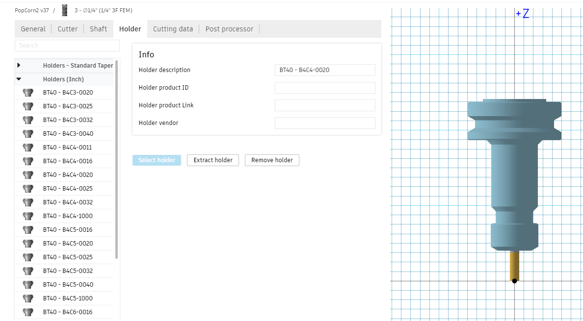
FWIW I use the stock BT40 holders when I am checking collisions for ER20 and ER16 tool holders.

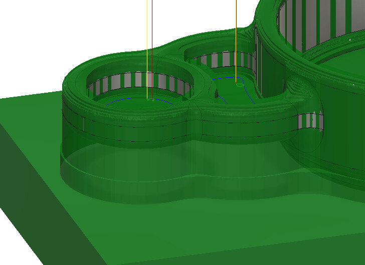
Scenario 2: I just didn’t pay close enough attention when I was setting up the CAM. Upon further inspection I figured out that I only need to cut into the part deep enough till I poke through the other side of the part as you suggested. This picture might help explain it

Wow that is the ultimate list of CNC learning videos! I have seen a couple of these videos while learning everything possible from YouTube so far. I’m sure this list will speed things along for me. Thanks!

Using the BT40 holders is good to know. And gotcha, that pocket isn’t as deep as the larger one to go thru. I hope the machine was alright after that little crash!

Oh the machine didn’t even know anything happened. I did learn that an ER20 collet nut will push aluminum around but it isn’t happy about it. The good news on this part is that I was already using material that was much too thick for this part (a piece of scrap I had around) so I just dropped z by 0.1" and restarted the part, skipping most of the roughing.
Happy watching (-:

Haha good! Well that worked out well. I’m working through the SMW online Fusion360 CAM course now. Working on programming my first part which is a custom step clamp for the vise and making toolpaths now.

Sweet! Good luck out there