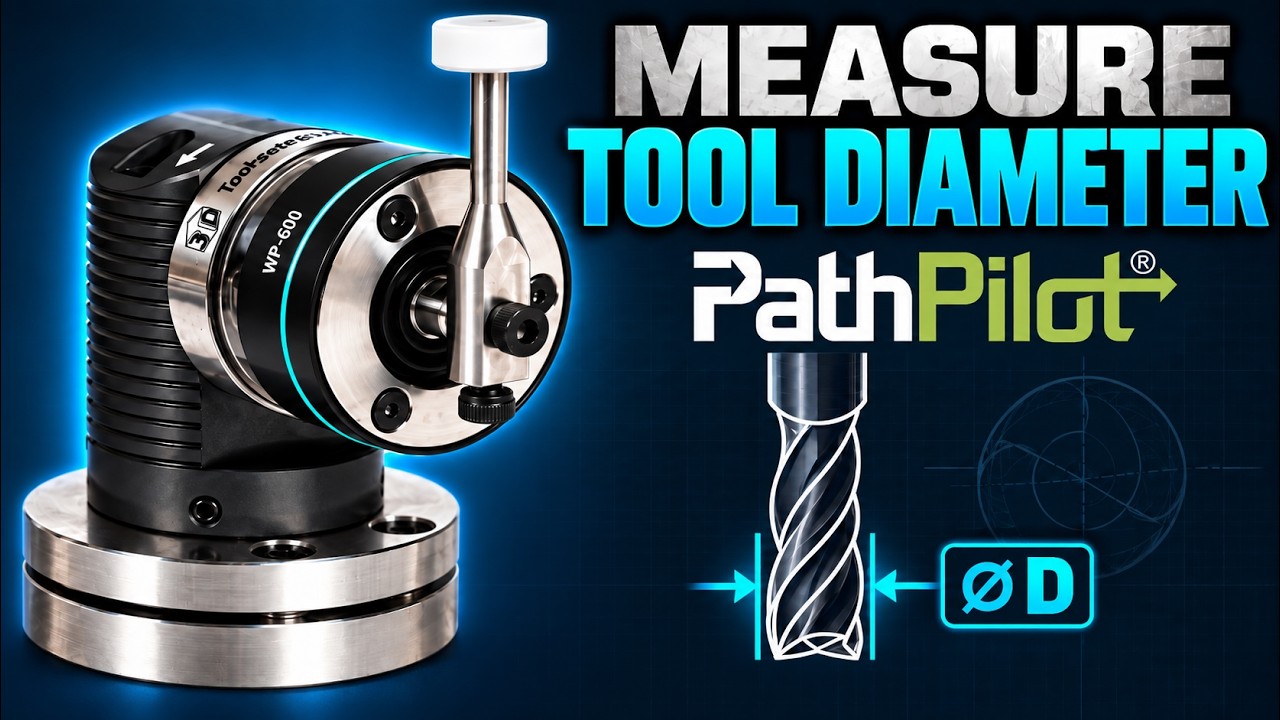
Length results were repeatable and they seemed to be accurate compared to the TTS height gauge and granite plate and I don’t have it noted but I recall also being on point to the simpler ETS I had.
I’m still working on diameter. I have a 0.008” DTI shipped to me to adjust the ETS to the spec that Renishaw calls for (0.0005” isn’t enough for their spec of flatness with respect to XY plane). I also need to check lost motion and whatever else may be contributing to errors in XY motion. There are also the limitations of being on a stepper-driven 440.
So far, it has been able to tell me that my 3FL 1/2” EM is not 1/2” at the tip (most likely from using it with over-optimism of the 440’s spindle power).
That sounds like a pretty interesting add-on. How hard is it to install on a Tormach mill and does it plug into the standard probe connector? I have an 1100 S3 if that makes a difference.
Do you know of a comparable tool probe for the 15L?
Funny, i usually take the mititoyo calipers and measure the diameter. Most of the time its at least a half thou under. I adjust it in cam software and with a spring pass, I’m pretty close to dead on.
It is an active probe. Depending upon the specific machine/version, you may need additional wiring. This one calls for 24V.
I found out that it is sensitive enough that it can trigger during machining (either vibrations or cutting or the jet of flood was tripping it). Setter/probe moves during machining shut down motion and the spindle instantly. I have it routed through USB I/O to disconnect it while machining. More recent PP releases indicate there are M codes to disable the tool setter and probe inputs via software and would be a better option.
Not a lathe guy (yet). On the $60k+ lathes, I have seen what looks like a standard touch probes mounted in the turret and tool probes that are similar 3D touch mechanisms mounted on an arm that extends out to a fixed position that the tool touches off against and it’s about a $6k option…
Is the probe only active while tool setting? If so, machine vibrations and coolant splashes might not be a problem. A video of it showing the workflow to sett a tool length and diameter would be interesting.
I don’t know if the 1100 has a 24 VDC PS or not, but it should be easy to add one.
On the lathe toolsetter, Robin Renzetti has posted some interesting Instagram videos on the toolsetter he designed and built for his 15L.
Inputs are active during machining unless explicitly disabled by the M codes in more recent PP versions (or you have to do what I did with the relay and M codes to switch it off at the beginning the machining cycle and then restore it when it completes). A stray signal from a probe or ETS on that input will result in both the spindle and motion stopping immediately. I am not the only one to note this issue.
The video posted is approximately what would occur for both a length and diameter measurement. I did not assume length from the tool table (the idea being you put a new tool in and you only enter the tool diameter in the tool table).
If the tool already has values, then comparisons would be made and depending on delta, you either update the diameter offset and length for wear or you error and flag the tool as broken.
There are definitely refinements to be made to the movements as the current program is not production and has more safety margins and conservative feeds until proven out further. I am still working through the setup/calibration/testing and math/geometry.
I think the result for me, when I’ve optimized eveyrthing that I can, is that the tolerances of the 440 motion will end up being the limitation rather than PP or the ETS and that machines with better motion control and/or precision will be more suited to full use of this.
I am trying to gear up for some small production runs of a product I’m trying to bring to market, so the extent I’m looking for is an automated log of tool length and diameter over time.
I didn’t even get the probe for this feature. I ran out of work envelope with two 4” Tormach vises on the machine bed. There seemed to be no location to put the “simple” ETS I already had where it could be reached to do tool lengths.
It is a ceramic disc and I haven’t looked for spares. I have just started to run it against a moving tool.
I’ve been looking for this as an option for a while now. Always felt like it shouldn’t be “that hard” to implement but I’ve not dug into macro programming in PP yet. In any case, well done, I look forward to seeing more on this front as you continue to develop it.
Couple questions: Since you are running a 440, I know that spindle reversing isn’t baked in, but since you have USB I/O, are you running the diameter check with the spindle forward or reversed? If forward, I STRONGLY suggest you check out David Loomes’ post and get spindle reversing set up. That will not only save your tool, and your probe, but may very well give you better measurements.
Along the same lines, there’s a lot of chatter happening during the diameter measurement (which is where the forward v reverse question comes from). If you are running in reverse, you may consider upping or dropping the spindle speed a bit. The vibration is very likely causing the probe to deflect more than it should be which will definitely cause measurement errors.
That was what I initially thought when I started. It is not proving to be quite “that simple” once you start getting output and comparing.
I’ve been running reversed the whole time. I would understand the ceramic is wear resistant but running an EM forward against anything, seems like a bad idea…
It depends on what size EM is being measured. On a smaller EM you don’t hear the chatter. Right now, I am running pretty slow in high belt. I have not tried varying spindle speed to determine impact on measurement given I’ve got several other variables that I have been optimizing. Once those are settled, I can look at RPM vs. EM diameter.
Thanks for the added details and thoughts Ashraf. For now, I’ll just stay with my current approach - measureing tool length with a height gauge and diameter with standard and V-anvil micrometers.