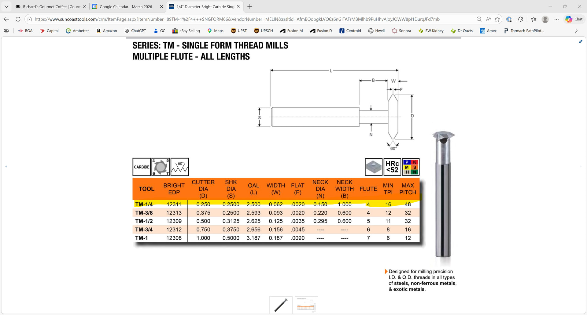
This is my first attempt at threadmill and hope someone can check it out. I would like to thread mill a 1/4-20 thread on a 1/4” diameter aluminum shaft. The details of the thread mill are noted below. I plan to use Fusion to set this up. Few quick questions:
- Setting up the tool in Fusion had a small error. I understand the flute length to be .062”. I got an error unless I entered .0625”. Not sure if this really matters.
- Pitch Diamter Offset. I downloaded the spread sheet from NYCCNC (see below). The first tab (Common Size Calculations) yields a PDO of .0713”, The “External Simple Tab” yields a PDO of .0824”. Looking at the simulations, the larger PDO value makes a thread with a sharp peak. The smaller figure yields a thread with a flat at the peak. Do you know which is correct.
Thanks… Richard
PDO Spread Sheet: Dropbox
Fusion File: Quarter 20 Threadmill Test.f3z (3.3 MB)
Thread Mill Details:
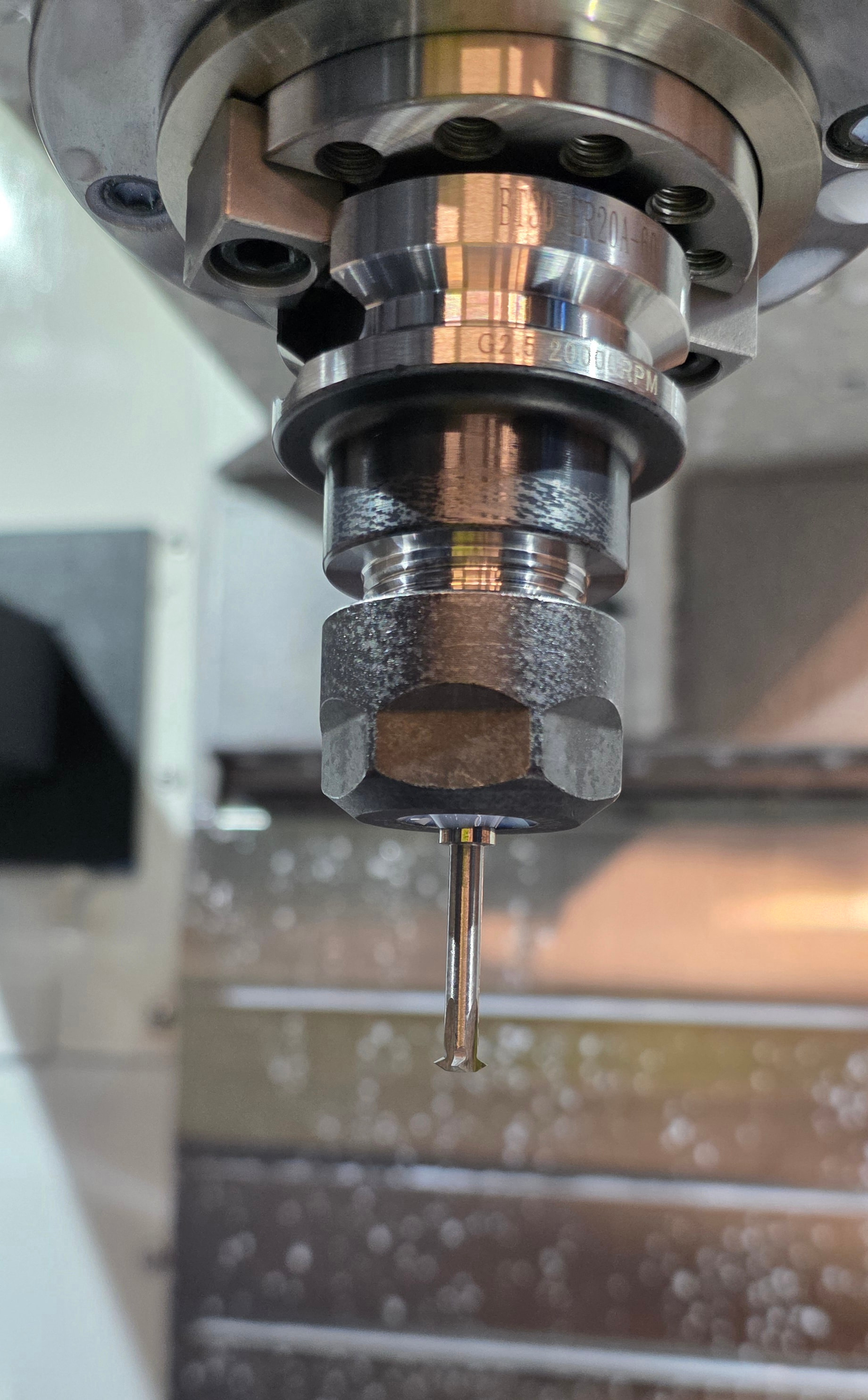
It’s a guts check the second time you press the start program on a thread mill and watch the $100+ tool hopefully not break. I say second time because the first time you didn’t know and it definitely broke.
I found the video that accompanied the spreadsheet on threadmilling. I included the link below. As noted in the video, it worked perfectly the first time. Quick overview of my steps:
- The WOC is simply the 5% of the thread mill cutting diameter.
- Number of passes should equal ((PDO/2) / (Cutting Diameter * .05)) rounded up to the next whole number or the (PDO/2)/WOC
- There are two tabs on the spreadsheet. “Internal Simple” and “External Simple”. Use the one corresponds to your internal or external thread, enter the Major and Minor diameter, cutter diameter and the width of the flat section of the thread mill and your done… is outputs the PDO.
Hope this helps…. Richard
Video: NYC CNC – Saunders Machine Works
Glad that worked out for you. NYC CNC videos are quite instructive.
IIRC, I used the same video/sheet. Straight threads worked like a charm, much like it did for you. NPT (tapered) did not quite work the first go round for me. It is queued up for me to revisit that.
On the subject of threads, Fusion will happily model external threads, but the CAM module does not deal with them like internal threads..
At least for internal threads, if you model the threads and the thread mill tool is properly defined, you should be able to simulate and at least have a decent idea of how successful the tool path will be, no? The modeling of the thread mill is the challenge. I’m in the process of doing this now for a 55 degree TM to cut PT / BSP tapered and non-tapered fittings for a coolant nozzle as well as my China MQL stuff.
1 Like
I did some further experimenting. The good news is that the threads work and it appears that the pitch diameter offset is accurate.
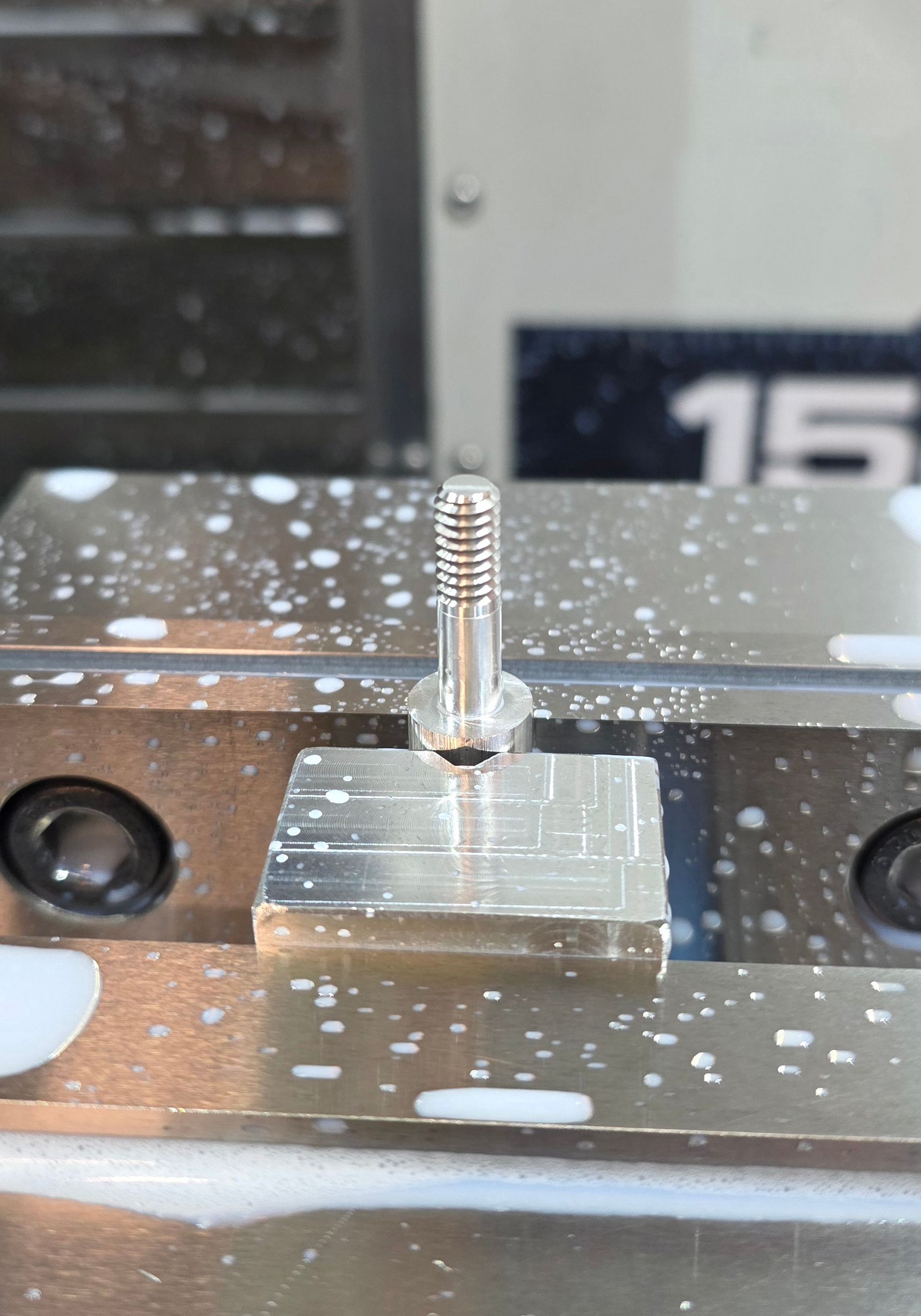
My first attempt at thread milling was to use PathPilot conversational. I attempted a similar part as below, but it only had .25 inches of thread as opposed to the .5” of thread below. When I cut the threads, it sounded fine and looked good, but the threads did not work. Norman at Tormach suggested I try it with Fusion.
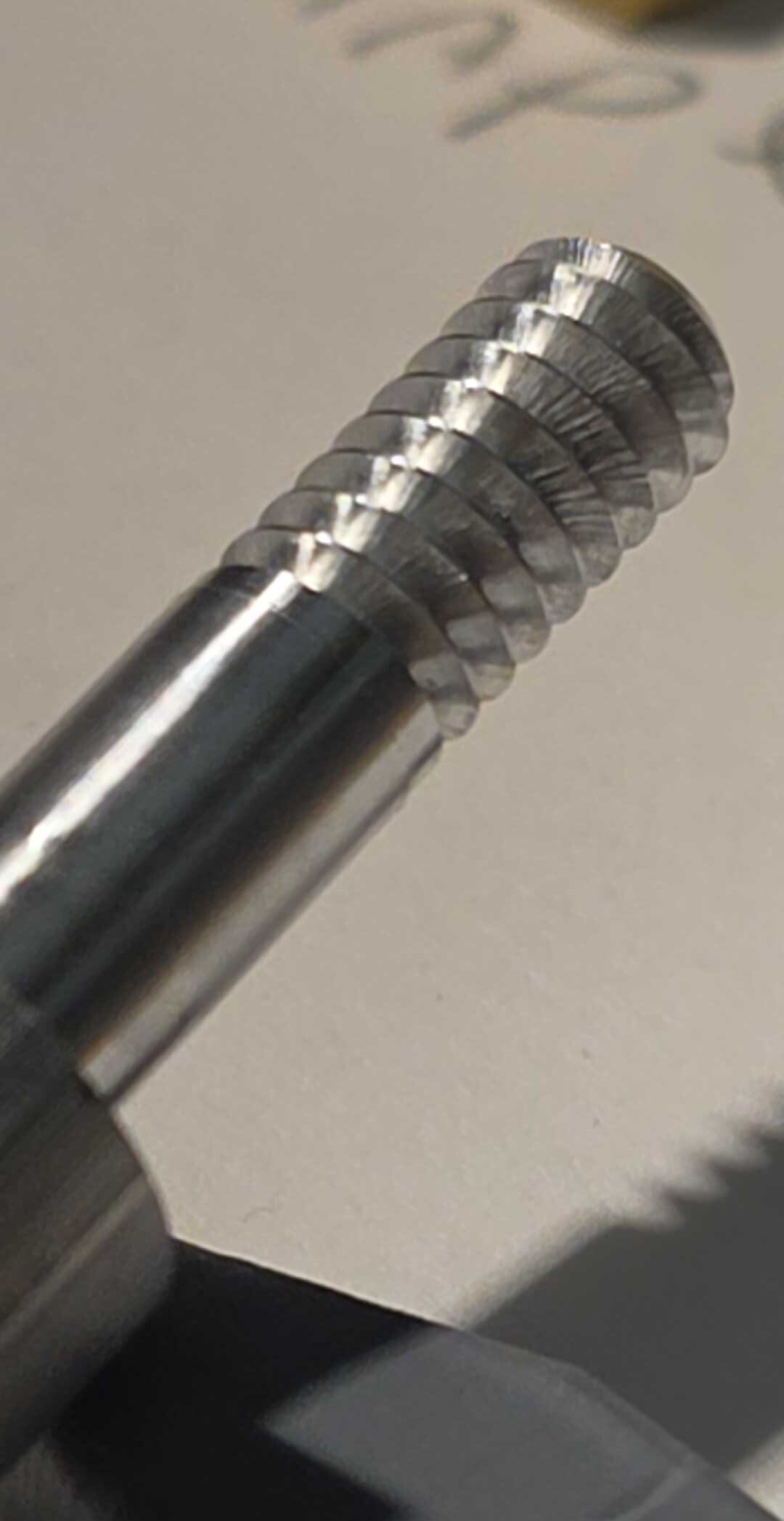
ran the 1/4-20 threaded 60601 aluminum part show below using Fusion with the same feeds and speeds and depth of cut per pass x a total of 3 passes. For some reason while running this with Fusion, I heard a fair amount of noise while machining. I did not hear that with conversational. Under magnification, I see what looks like chatter to me. I am a bit lost here because I am attempting to replicate what I did with conversational. One thing I noticed was that the first pass did not cut almost anything.
Any idea what is causing the chatter? Is it because the threaded area is longer? I tried lighter passes as well and had the same issue.
Details: PDO = .077”. 3 step overs of .018”
File:
CAM Shaft Small Qtr 20.f3z (3.3 MB)
Thaks… Richard
Is the part aluminum and the v block aluminum? Try a bigger groove to get the round bar in there farther. Because it’s aluminum it’s going to flex. If you can cut just the thread part and then threads and then the rest of the shaft. If it’s steel you could do it the natural way.
Here’s an idea: post the threadmill GC op from Fusion by itself and put that with the PathPilot GC for threadmilling into the same GC file and look at them in the 3D preview to see what/if there is a difference in the toolpath.
I was initially thinking if you could put them both in Fusion but it doesn’t simulate GC it didn’t generate.
There are two free tools, NC viewer and NC-Corrector that may have more inspection tools that what you have at the machine or on a Virtual PathPilot instance…
Before commenting on the surface finish or “chatter” you mention I would ask what the speed and feed were for the cut.
I’ve noticed similar marks in internal threads I’ve cut and always attributed them to just running the tool too fast for the spindle RPM. Tool vibration could be a cause but definitely not part deflection in that case. The threads work fine and pass go/no go testing but I suppose it wouldn’t hurt to have a smoother finish. For reference in a 10-32 internal thread I’ve been running 40 IPM at 10k RPM. I’ve switch to rigid tapping for the most part now and haven’t thought much about going back to revisit the finish. I’ve read that form tapping in aluminum is the best approach, of course that doesn’t help external threading too much.
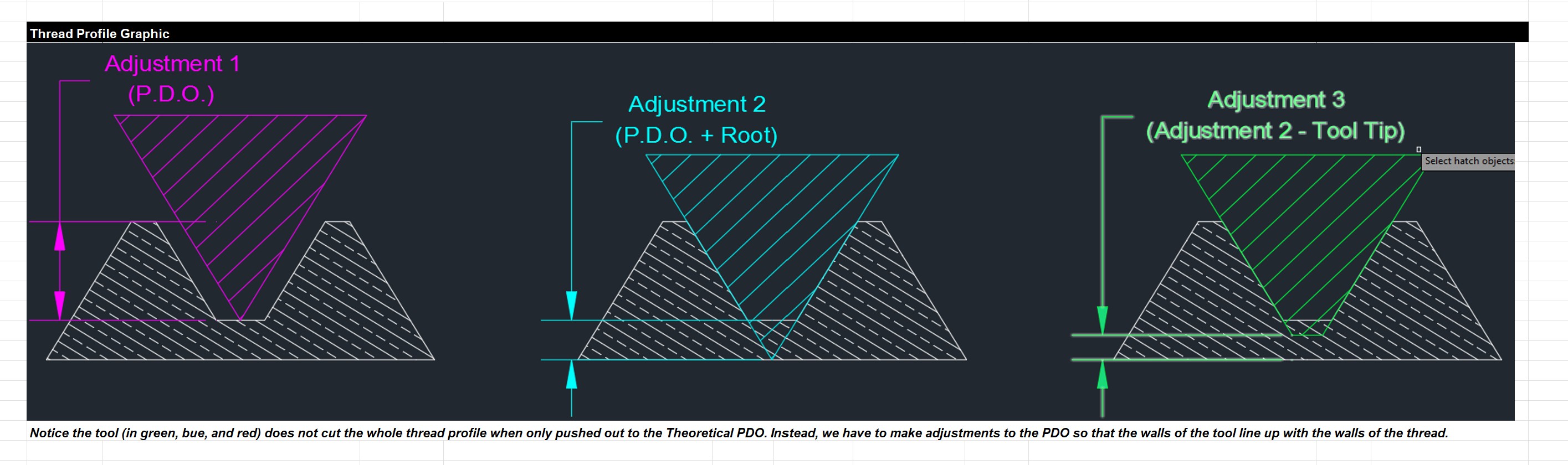
You need to remember that all thread dimensions and definitions are not for sharp, V shaped tools - like all treadmills. The definitions are to the thread flat ( or what you called rounded). You need to calculate the root and crest distance and ADD that to the thread dimensions if you want an accurate thread.
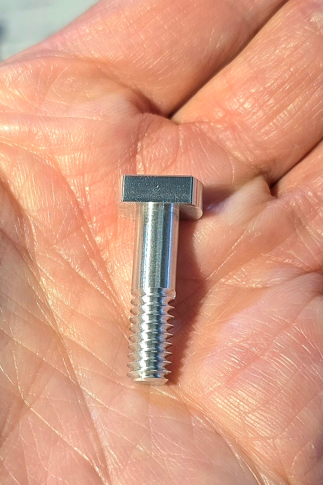
Hey guys, thanks for all the great tips. I modified the tool paths to machine the threads first, dropped the rpms from 9720 to 9000 and it came out great.
Dan, for what it is worth, the NYCCNC spreadsheet does exactly what you described. You input the major and minor diameter, thread mill cutting diameter and the thread mill flat or crest dimension and it outputs the pitch diameter offset that accounts for the fact that the thread mill does not in fact come to a sharp point. Check it out if you are interested.
Graphic from NYCCNC:
Finished part: