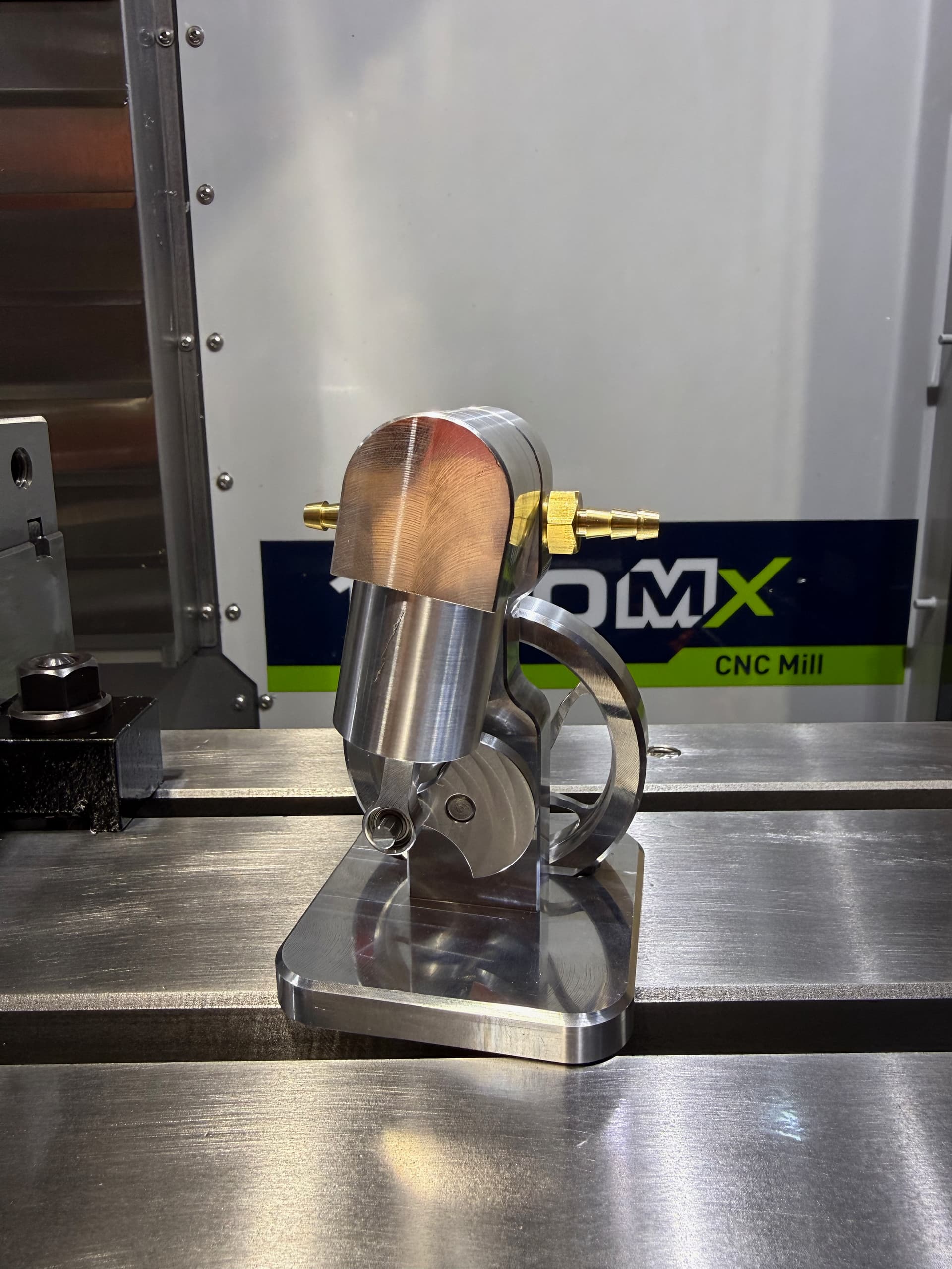
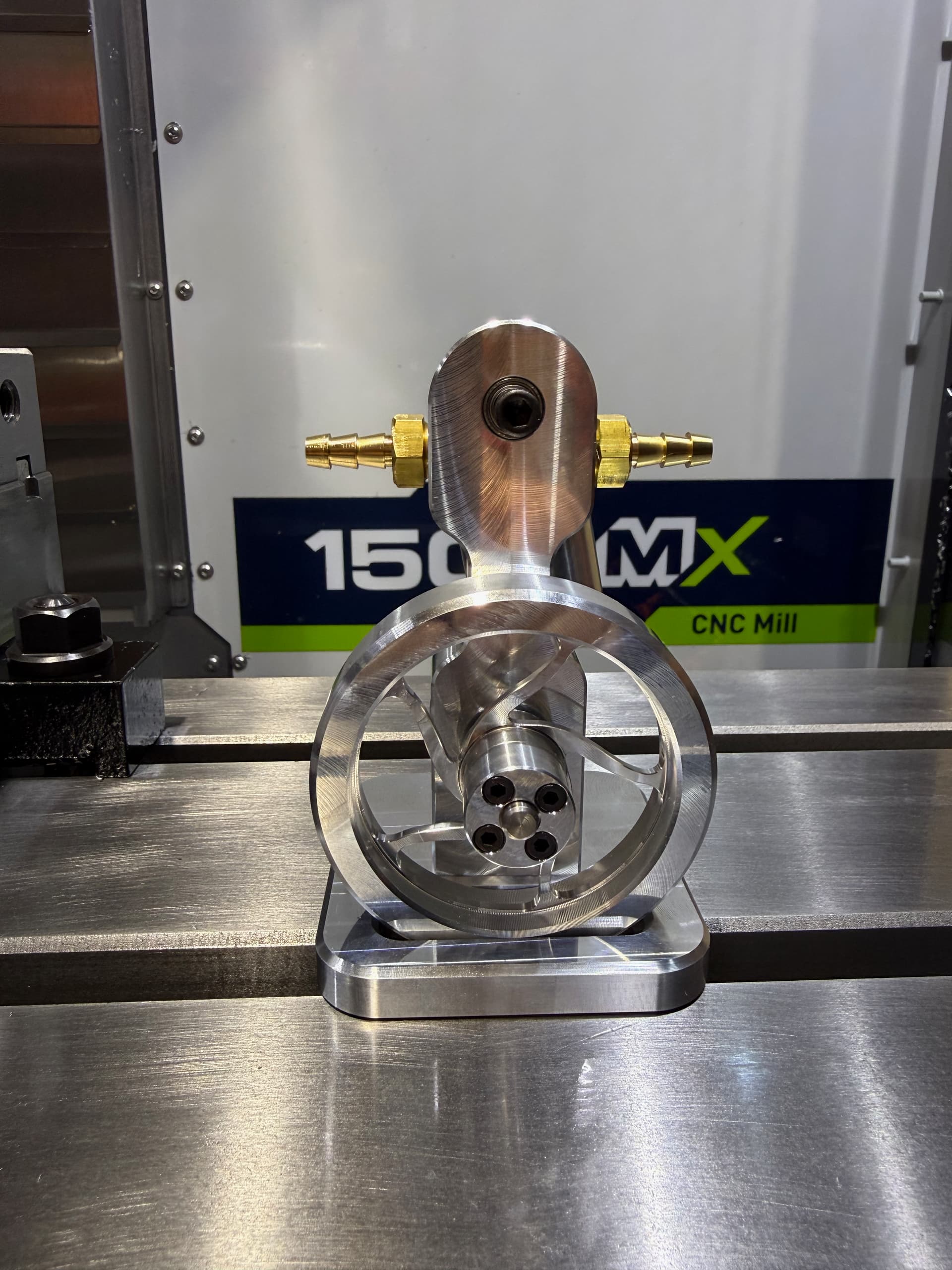
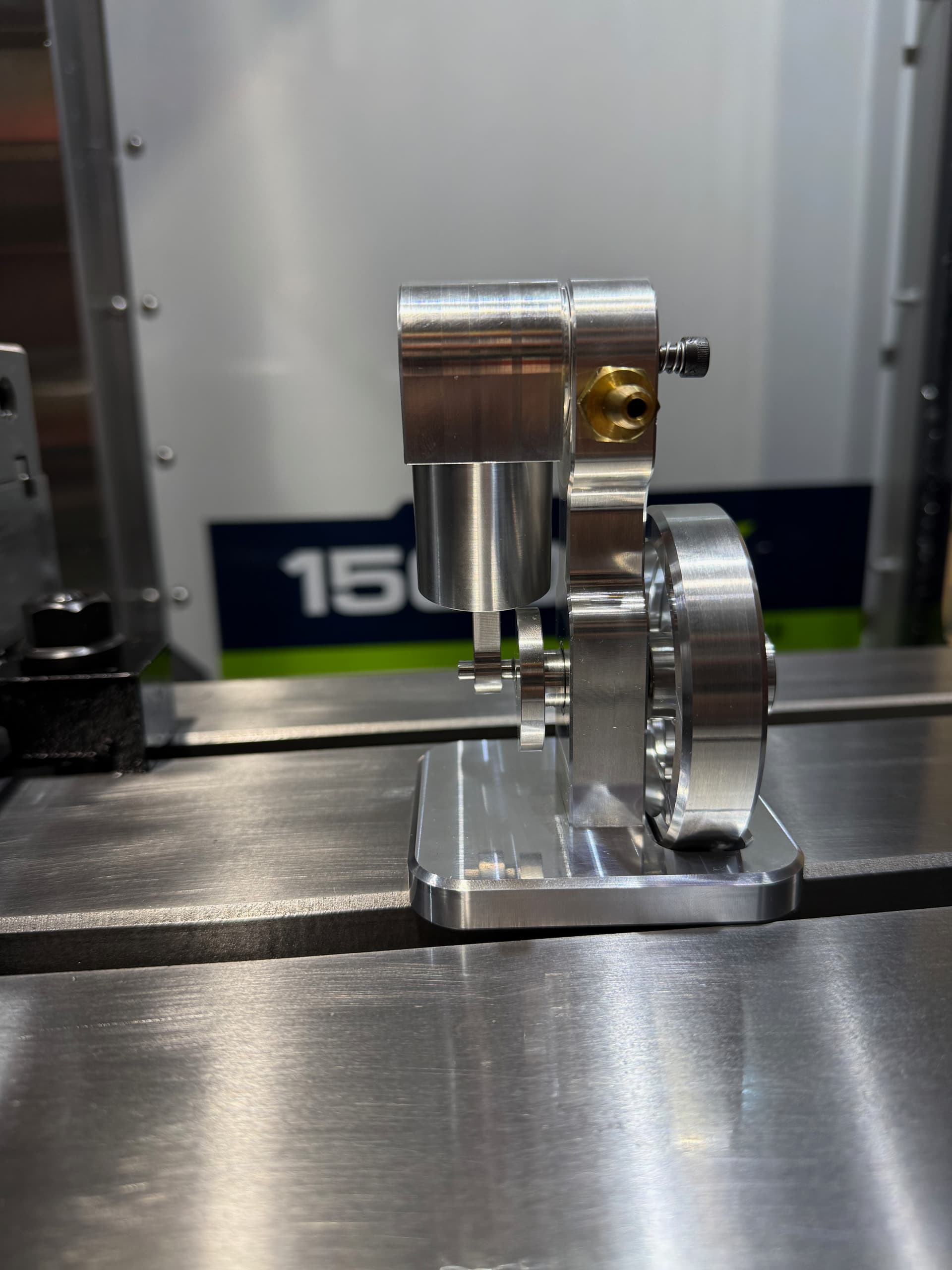
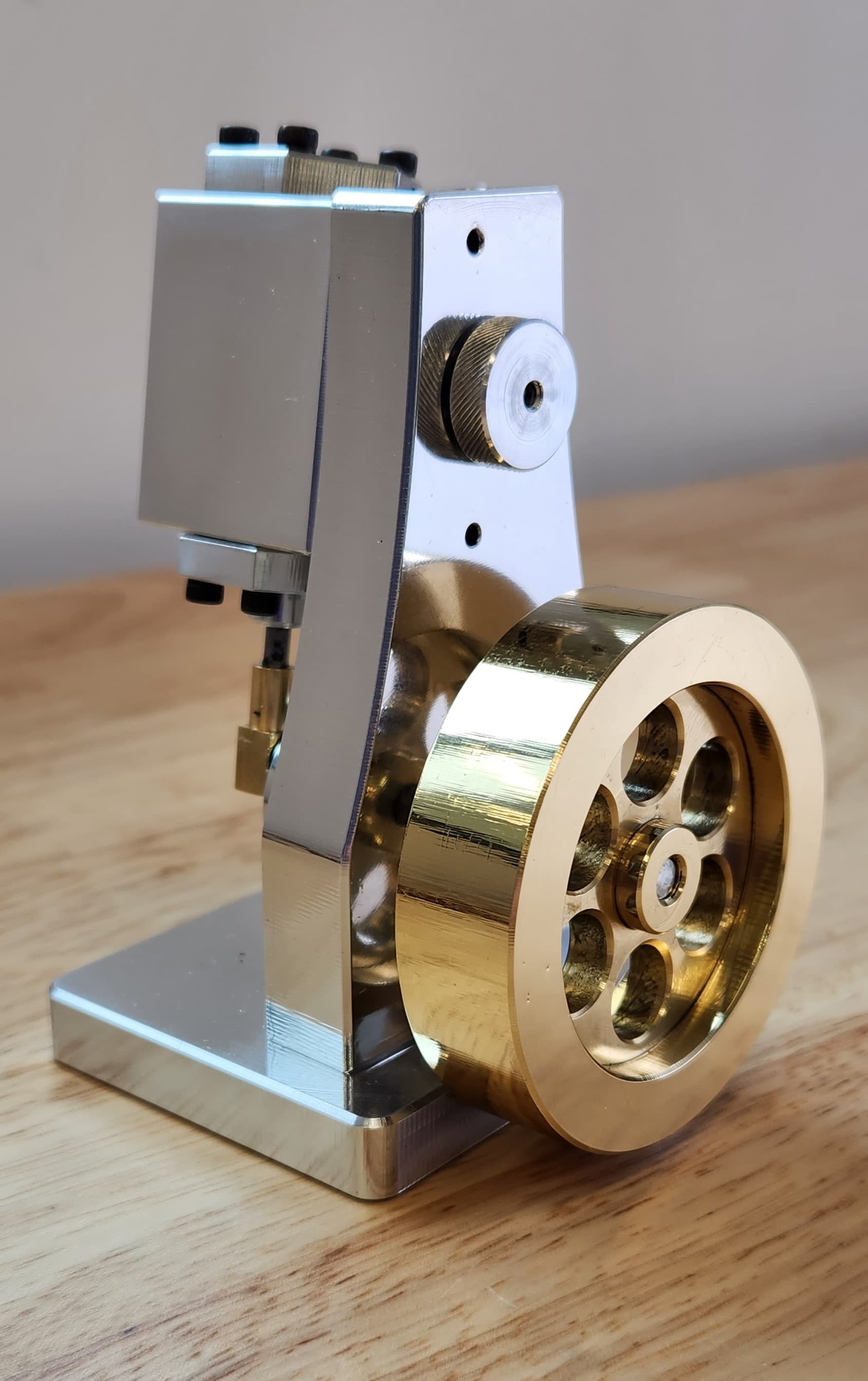
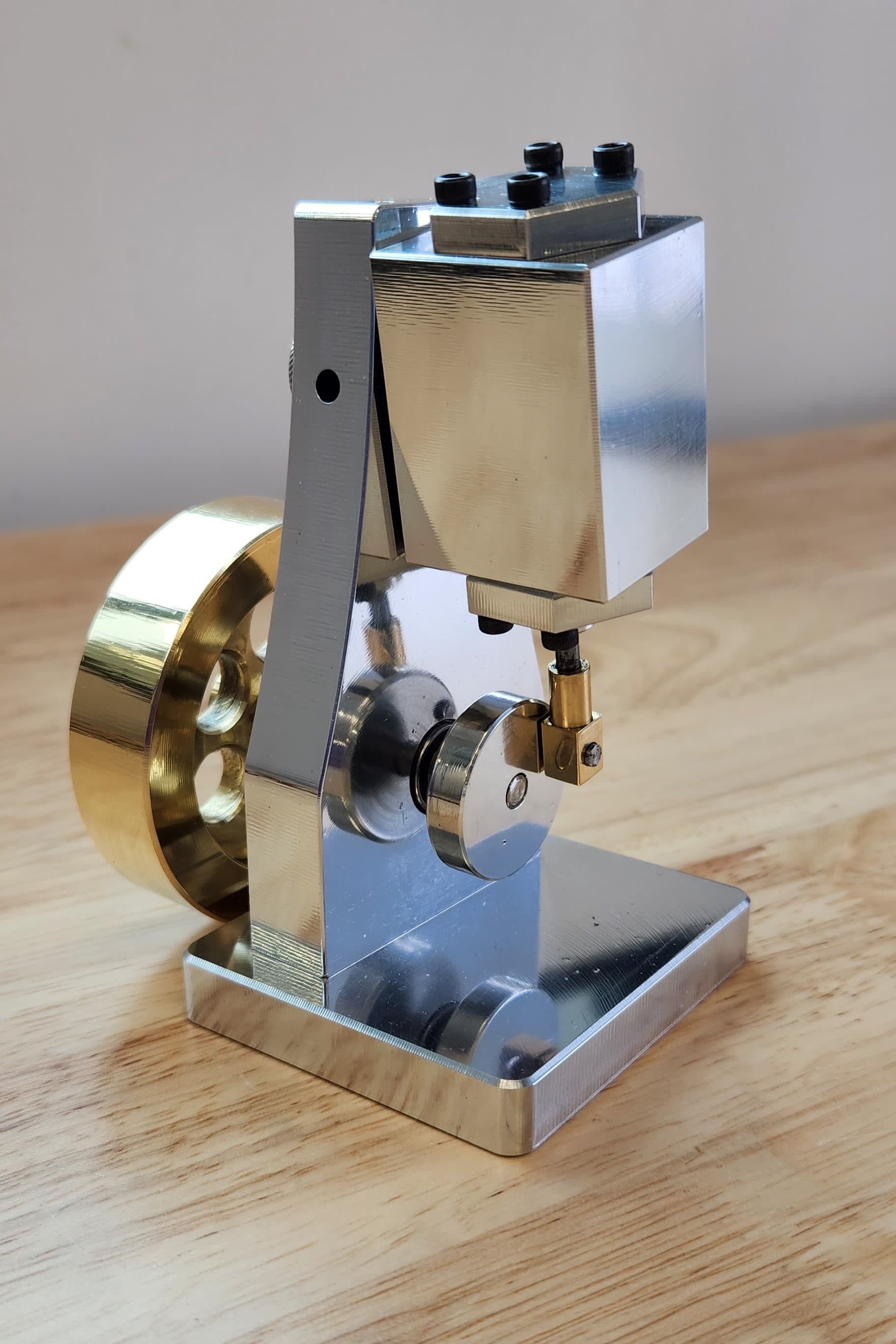
I’ve been making odds and ends for Christmas gifts for years but thought this year I would see if I could scale things out a bit. With the recent addition of a 1500 MX mill to the shop it seemed like some automation could bring the quality up and labor down. I had an old design for a basic steam engine that was made on a manual mill and lathe years ago that I intended to model and CAM for the 1500 MX. It became obvious early on that not only was the design primitive but didn’t lend itself to CNC. I used the same principles from the early engine but started with a clean slate leading to what is pictured here. Starting over was definitely the right approach for this project.
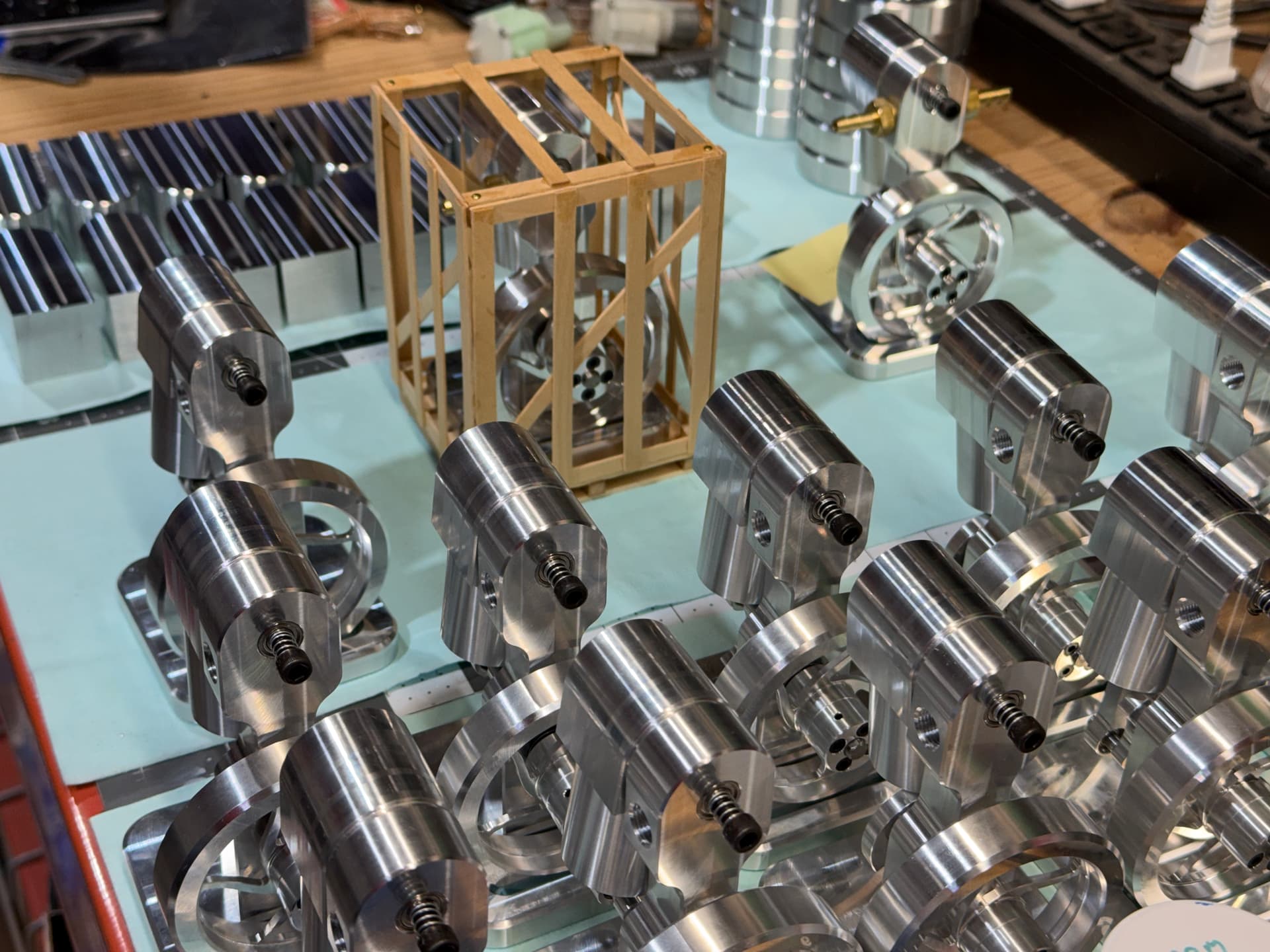
All of the parts were made on the 1500 MX with the exception of the spring, bearings and fasteners. Most is 6061 aluminum but the piston is Delrin, the air fittings are brass and the main shaft is steel.
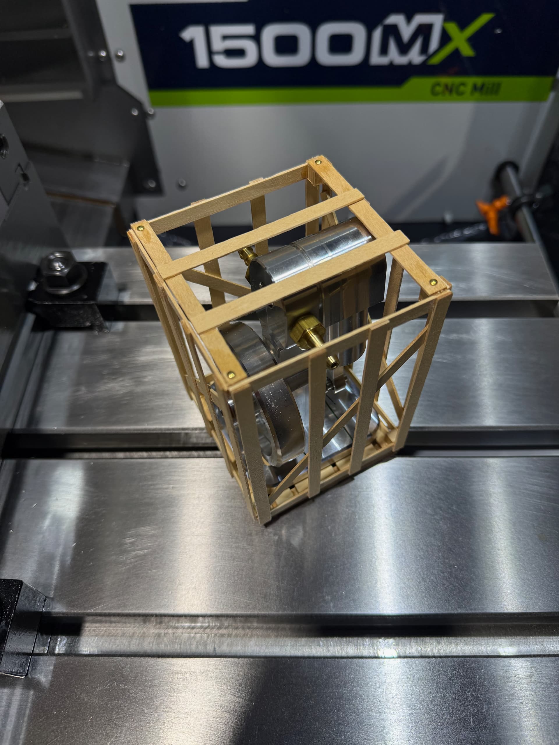
I’ve given most away as Christmas gifts and they have been well received. One of the engines got a custom wood pallet and crate inspired by the Tormach 1500 MX packaging.
Working on the CAD for the USS Monitor steam engine. Not the fancy one. Couldn’t find the plans for it. They must have removed it from the website. I’m modifying a lot of the parts so they don’t look so blocky. Kinematics are spot on from the prints though. Good starter model.
Absolutely love this build! The shape and sizing really gives it a hefty feel, and the cutaway base is a nice touch.
Are you mostly gifting to people with access to compressed air? I’ve been thinking about doing a run of engines, but that’s been one of the things holding me back. Maybe I’ll try flame lickers or something.
Most people use an air compressor although to be honest I suspect a few will just admire the model on a shelf and may never run it.
The model is pretty forgiving about low air pressure. I was testing them after assembly with about 2-3 PSI and they loaf along pretty smoothly. The Delrin piston, close tolerances and ball bearings throughout make for a low friction engine. The cylinder was bored using a 15/16 reamer that I modified for TSC by shortening and drilling a hole through lengthwise. A fine boring head might have been a better choice but pricing was higher and this seems to work pretty well. I don’t have a tool to measure surface finish but it’s pretty smooth.
I love everything about this project. Did you employ a fixture for these or is this all vise/ soft jaws territory?
I know little more about steam engines than what I have seen on YT so please forgive my ignorance. The steam is coming from a different source and pumped into this engine?
I didn’t use a fixture for any of the parts. All first operations were done with TalonGrips or VersaGrips and then subsequent steps done with soft jaws or smooth. A few items were held in a small lathe chuck I have mounted to a plate that allows me to easily hold it in the vise.
I was considering fixtures for some of the pieces and if I was going to make more I would probably go that route to increase cycle times and reduce babysitting of the machine. For a lot of the smaller parts I was able to fit multiple of them in a single soft jaw. I had a few concerns about holding more than two parts at a time so this was mostly done with the plastic more compressible pieces. The metal parts were done two at a time if size permitted. Like wise, I was able to hold two pieces of raw stock at a time for the smaller parts reducing machine load, unload time. I was doing other stuff on the mill during this project so I had some interest in keeping the vice in place.
For simplicity I used multiple WCS for the two up parts. I found it easier to just set the two origins in G54 and G55 then tell fusion to run the job in both. For instances where more than two pieces were being machined I used the Fusion pattern feature to handle the multiples. This worked out well when there were soft jaws that would space the parts evenly and had an easy to reference origin. I suspect more advanced fixturing would fit great with the patterns feature.
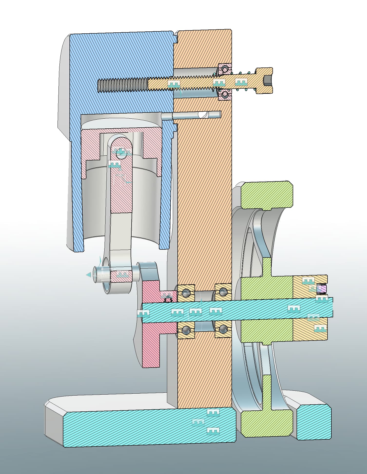
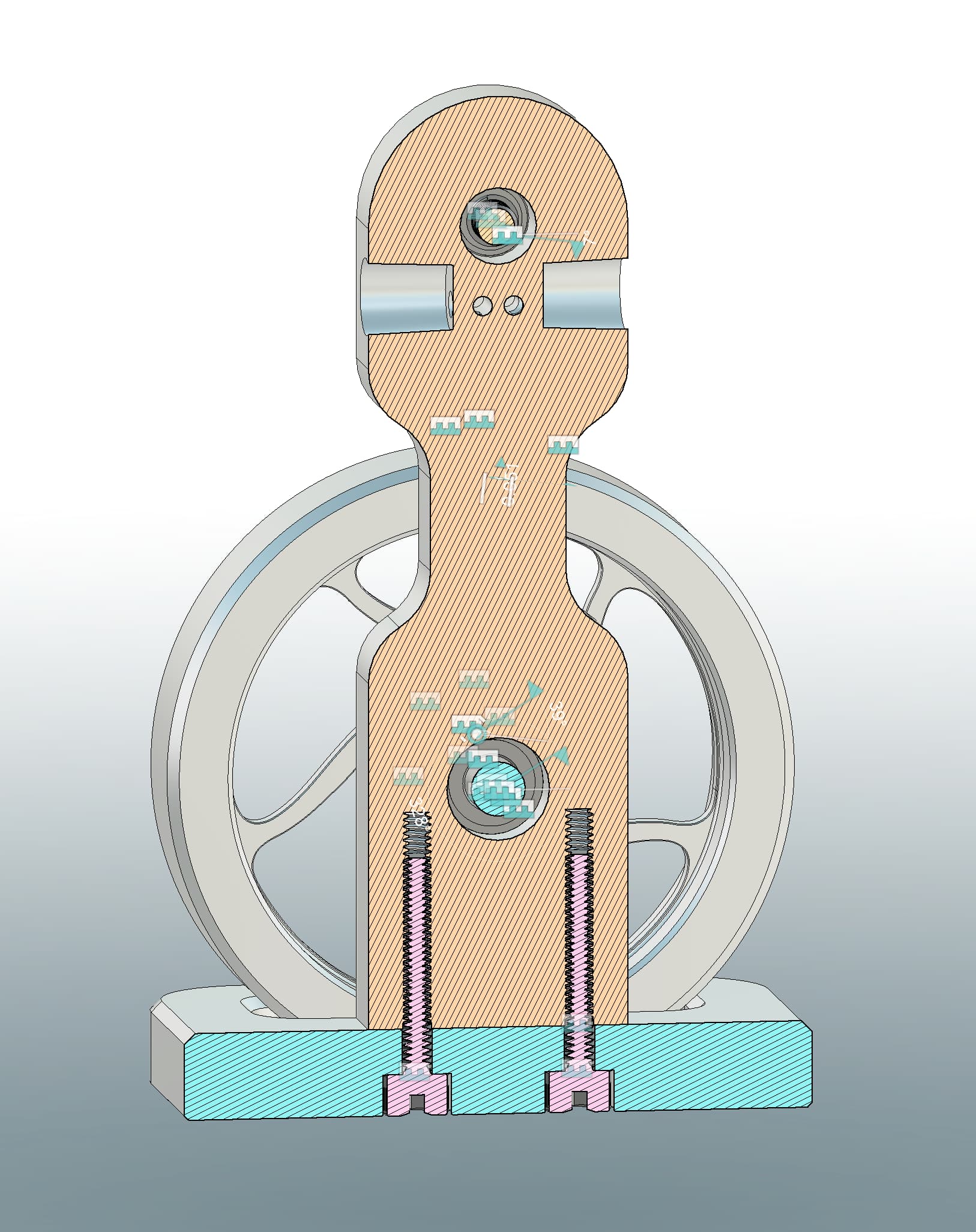
Any of these little “steam” engine models are usually run on compressed air. For this engine at least compressed air can be connected to either port. The direction of rotation will depend on which is used as input and which is used as exhaust. The simplicity of this engine design is that it only has pressure applied to one side of the piston. Usually steam engine pistons are powered in both directions. Because of the single sided behavior in this engine the flywheel must hold enough energy to complete an exhaust stroke and return the valve back to allow compressed air into the cylinder. I’ll see if I can get time to add a couple of cutaway views of the engine so you can get an idea just how simplistic this is.
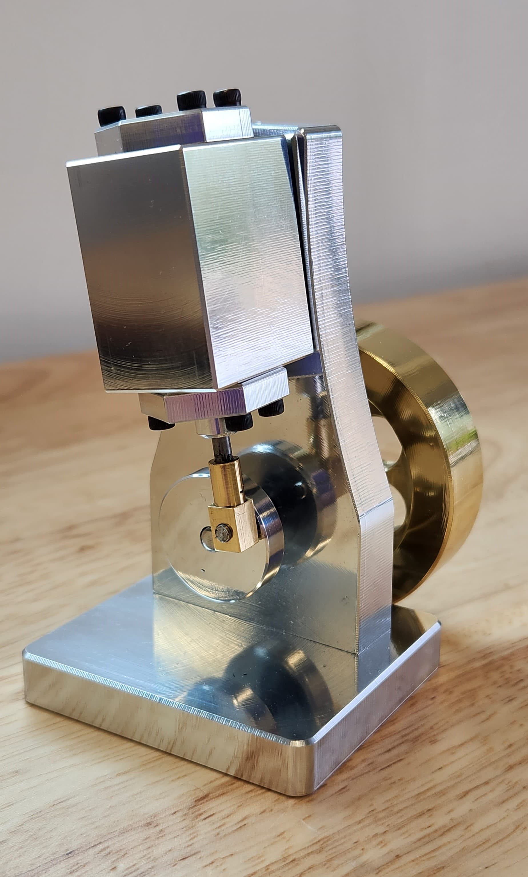
Really nice work and cool design! Over the last three years, I converted a manual mill to CNC. When I finished the conversion, I took a simple steam engine design from Mr. Pete on YouTube and sketched it up in Fusion. With the exception of the knurled thumbwheel, I made every other part on my converted mill (see below).
I just rec’d my 1500MX and thinking of what kind of cool project to get moving on. Just curios, did you design that nice steam engine yourself? Do you know of anywhere I can get similar plans? I am still thinking of jazzing up the one I made and making a slightly bigger fancier model, but I am so excited about machining something that I’m not really in the mood to start designing another model from scratch.
I recall seeing the project Mr. Pete did a while back, and yours is certainly a fancy take on the original.
I started with a similar situation for the engine I shared. I had long ago made a few on manual equipment and decided to try to move the project to the Tormach. The original was mostly slapped together piece by piece with trial and error. Once a working prototype was completed, I made some CAD drawings to work from and turned out 6 more. It became obvious that a clean slate was the way to go, at least in my case. The entire design was created from scratch in my spare time with only the original model as a guide. Version 2 was mostly proven out in Fusion simulations. I did have to make a couple of on-the-fly revisions after getting a working prototype, the most significant one being a move from aluminum to acetal for the piston. Conveniently, the acetal machines fine with the same CAM and tooling used on the aluminum part, although it’s horribly inefficient, I’m sure.
Given the spare time nature of the project, coupled with the mad scramble to finish by Christmas, I’m afraid the CAD/CAM is a mess. I’ll look it over when I get a chance, and if I think it can be cleaned up without too much pain, I will reach out to you.
For your example, it seems like you already have done the design and CAM. I would be interested in seeing what that model looks like reimagined on your new hardware.
Funny, I can assure you that my drawings got a bit messy as well. I started in this hobby about 3 years ago and found learning CAM, CAD and machining all at the same time to be a bit of a challenge. This was my first real project on my converted mill, and it was quite the learning experience.
I do want to make a larger, fancier variation of the steam engine on my new 1500, but now sure I really want to spend the time it takes to start from scratch. I have a few other ideas of making something with gears that move but I really don’t have a definitive idea for my next project.
In a perfect world, I would love to find a completed design and focus on the machining part. Right now, I am just looking for anything interesting to make.
My last project was a carousel ATC for my converted mill. That was a real technical project, and I’d like something a bit less technical. For that project I machined a bunch of Delrin and I found it to machine almost identical to 6061. That stuff is expensive!
If you see any fun ideas, please shoot them my way.
Here’s a copy of drawings for a marine steam engine that I re-designed, modelled and drafted plans for, if anyone would like a copy of the fusion file, please feel free to drop me a line on here.
I’ve just bought a 440 and will be machining the engine in due course..
That is really beautiful. Are you planning on machining all of these parts on your 440? I would definitely be interested in these drawings. Looks like a real fun project! Thanks for sharing!
Iam indeed going to machine the entire engine. This started about 4yrs ago when I began dabbling with a manual mill, since then I got sucked into CNC…. .
I’ve been interested in fusion for about 10 years, the 440 is my first experience with CNC, I’m based in the UK and have had my 440 imported through a Tormach re-seller in the UK I’m waiting on delivery in the coming weeks.
I’ll send you the fusion files, I’m more than happy to sure, as I’ll no doubt be on the forum looking for advice at some point.
Cool. I made one of these “bogstandard paddleducks” engines a long time ago. Fun project although the instructions for timing the eccentrics was a bit confusing.
Hey Martin, I finally got a chance to download your drawings and WOW!… Really nice work. I will be giving this some thought as this may become my next project.