Setting Tool Length on Large Facing Cutters programmatically

Has anyone figured out how to programmatically set the tool length of a large fly cutter or facing cutter?

For all of my tools smaller than the face diameter of the ETS, I wrote a simple subroutine to call G37.1 and then G37 to set the active tool length immediately after a tool change. What I would like to do is pass a variable to the subroutine to move the X axis away from the center of the ETS ( 38.1 mm for a 3" facing cutter for example) so that after the call to G37.1, the system could call G0 X#1 (-38.1 for 3") and then perform the second half of the G37 command without returning to the saved ETS X,Y, and Z locations. Kind of like checking the “Z Only” box on the Offsets Tab. I can’t find any help in the “Mill KB”.

Manually, I remove the Facing Cutter from the ATC, and then “Touch Off the Entire Tray” at the start of an operation. I then return the Facing Cutter to the ATC and then move the X axis -38.1mm and check the “Z Only” box for that one Tool.

Looking forward to an answer here as it would probably solve one of my biggest gripes with the G37 cycle. Because of 1 or 2 very long tools I have my G37 start position set quite high which wastes a lot of time for every other tool in my library. Unfortunately, the variables that contain the G37 XYZ position aren’t exposed to the user because my intention was to create a macro that would alter the G37 position on the fly based on the current tool length for a given tool. Something like + 1" = , G37, = .

The same approach would work for your application, just replacing Z with X (or Y) and tool length with tool radius.

I thought I had found a solution to this since I found that the ETS X and Y Values are stored in #5420 and #5421, however they are Read-Only persistent values and can not be changed on the fly.

Jeffrey,

There’s not currently a good solution to be able to use large tools with the “touch off entire tray” button. You can specify an M19 command with a rotation angle (on MX machines) and add X/Y coordinates to a G37 command to apply an offset from the stored G37 position but those need to be done via MDI commands.

This is on the roadmap for development, but is fairly low priority vs the 2.12 unification and will likely added in conjunction with diameter touchoff for 1500’s. To nudge that work being bumped up the priority list I’d encourage anyone to submit a feature request ticket here to get the Pathpilot team’s eyes on it (they do not regularly monitor the forums).

Thank you,
Norman

Oooh! Diameter touch off?! I see you specified the 1500 in that comment but I do hope that will be made available to the earlier machines as well. Or at least not locked out for the earlier machines.

Ian,

Diameter touchoff is not possible on previous ETS models (they can only touch off in Z) but there’s no reason we can’t step over to measure the length of a large tool.

Thank you,
Norman

Thanks Norman, this is exactly what I needed. I was playing with G37 and realized that it required G53 coordinates, so I wrote the following subroutine and tester:

(---------------------------------------------------------------------------)
(Mill - set_tool_length_with_radius_offset.nc 7-11-24)
(PathPilot Version: 2.10.1)

o<set_tool_length_with_radius_offset> sub
( #1 radius of tool)
( #2 former tool length offset)
( #3 tool orientation )
G37.1 Z0 (go to ETS center location )
#10 = #<_x_machine> (get G53 value for ETS X value)
o1 if [[ #3 GE 0 ] and [ #3 LE 360 ]] (test for valid orientation)
M19 R #3 (lock spindle at desired angle)
o1 endif
o2 if [ #<_metric> eq 1 ]
#13 = -364.24 (metric location of ETS Surface below Spindle nose )
#14 = [ #13 + #2 + 19 ] (3/4" slow travel)
o2 else
#13 = -14.34 (imperial location of ETS Surface below Spindle nose)
#14 = [ #13 + #2 + .75 ] (3/4" slow travel)
o2 endif
G37 X[ #10 - #1 ] Z #14
o<set_tool_length_with_radius_offset> endsub

(Test Starts Here)
G17 G90 (XY Plane, Absolute Distance Mode)
G64 P 0.0050 Q 0.0000 (Path Blending)
G21 (units in mm)
G54 (Set Work Offset)
G30 (Go to preset G30 location)

T283 M6 G43 H283 (3" Facing 61 degree insert offset)

o<get_tool_specs> call (calculates #<_tool_radius> from #5410 and #<_tool_length> offset from #5403)
o<set_tool_length_with_radius_offset> call [ #<_tool_radius> ] [#<_tool_length>] [61]

T340 M6 G43 H340 (1/4" End Mill)

o<get_tool_specs> call
o<set_tool_length_with_radius_offset> call [0] [#<_tool_length>] [0] (small tool NO offset needed)

M30
(---------------------------------------------------------------------------)

Ian this is the answer to your few long tools problem!

2 Likes

I admit this took me way longer to read and interpret than it should have. I’ve yet to have a real need for subroutines so I just haven’t bothered to learn the syntax until now.

That said, all of this makes good sense EXCEPT the call to o<get_tool_specs>. Obviously that’s another subroutine but since it’s not defined in your sample program, I’m assuming it’s something else you’ve written and keep on your controller. Or is it a built in subroutine?

Ian,
The following is the content of the o<get_tool_specs> subroutine:


o<get_tool_specs> sub

o1 if [#<_metric> eq 1 ]
#<_tool_diameter> = [ #5410 * 25.4 ]
#<_tool_radius> = [ #5410 * 12.7 ]
#<_tool_length> = [ #5403 * 25.4 ]
o1 else
#<_tool_diameter> = #5410
#<_tool_radius> = [ #5410 / 2.0 ]
#<_tool_length> = #5403
o1 endif

o<get_tool_specs> endsub


1 Like

Norman,

When G37 was first added, I spent along time looking into this to add ETS support to my post-processor. I got stuck on this exact point because I could not get the X and Y options to G37 to work the way you describe.

I had another shot, experimenting with my machine, and ! think I can now see what’s actually happening. The X and Y values are not being used as offsets from the G37 position at all. It appears they are being used as absolute machine coords, so it works more like you might expect if you typed

G53 G37 X0.1

What I didn’t know back then was that the G37 location was available via #5420…

If you could confirm I’m correct about G37, then I can easily get the effect I want via

G37 X[#5420 + 0.1]

Updating the post-processor to generate appropriate code for large diameter tools isn’t difficult if I’m confident this is going to remain the case in future. I’m pretty sure this will handle the cases being discussed here.

Now that’s interesting because a while back I had commented somewhere that if the G37 location was available via a user exposed parameter, adjusting for long/short or large diameter tools would be trivial. At the time, I believe I was told that such a user exposed parameter did not exist. I even went looking in the linuxcnc documentation to try and find it there without success. I wonder if I just missed 5420 or if something has changed since my previous search.

If you look at the LinuxCNC documentation, the value of 5420 is documented as: " 5420-5428 - Current relative position in the active coordinate system including all offsets and in the current program units for X, Y, Z, A, B, C, U, V & W, volatile." It has nothing to do with the storage of G37 location variables unless you have just called G37.

I did see that back then and again today. I knew the stored position was based on G53 but didn’t realize that calling G37 would alter the current position parameters from the currently set WCS so I didn’t think that 5420-5428 would apply in any way. Based on Tormach’s documentation, it does seem that G37.1 can accept X and Y offsets but not Z.

Happened to be in front of the machine yesterday so I thought I’d play around a bit with G37 and offsets. Turns out G37.1 X[#5420+nnn] does not work as one would hope. In this context #5420 contains G53 X0 so the spindle simply moves nnn away from the far left of the table.

David,

#5420 is just current relative position, it isn’t tied to G37 in any way. I don’t recall any parameters for G37’s location. I’m not sure if specifying an X or Y coordinate with G37 will operate as expected, I’ll put it on my list to play around with but I won’t get to it for a bit.

Thank you,
Norman

Thanks Norman,

I know I remember looking at this quite a bit some time back and I’d have been really disappointed if I’d missed something as simple as looking up #5420.

The application I was interested in was checking each of the inserts on a face mill to get an idea of how even they were and I really needed to get the xy offset to work.

If it gets sorted in future, there’ll be an immediate use for it!

David

David,

You’d also need to be able to orient the spindle in order to touch off individual inserts, if only to know where the first insert is to make an XY pattern.

Thank you,
Norman

If you had a spring loaded, teardrop shaped piece of delrin attached to the side of the ets it could be shaped in such a way as to engage between the cutter teeth and rotate away from the ets as the cutter approached.


Should be able to use a pretty simple shape for most cutters. And you could always layer the shapes for different cutters and adjust the offset.

Are you building space shuttle parts?

I can’t speak for David but I always check every insert on my face mills. They’re usually only off by no more than .0015-.0025 but if I don’t set my tool length based on the longest insert, it’s entirely possible that I end up with thin parts. While a couple thou is generally within tolerance, I have worked on parts that needed to be held tigher than that.

1 Like

The following code contains a subroutine which allow me to measure all of the tool lengths of all inserts on my 2" and 3" facing cutters. All of the G37 and G37.1 calls work properly on my 1100MX.

(---------------------------------------------------------------------------)
(Mill - set_tool_length_with_radius_offset.nc 8-5-24)
(PathPilot Version: 2.10.1)

o<set_tool_length_with_radius_offset> sub
( #1 Radius of tool)
( #2 former tool length offset)
( #3 Tool Rotation offset )
( #4 Number of Inserts)

G37.1 Z0 (go to ETS center location )
#10 = #<_x_machine> (get G53 value for ETS X value)
#11 = 0

o29 if [ #4 GT 0 ]
#12 = [ 360 / #4 ]
o29 else
#4 = 1 (Default to 1 Insert with 0 degree offset)
#12 = 0
o29 endif

o30 if [ #<_metric> eq 1 ]
#13 = -364.24 (absolute metric location of ETS Surface below Spindle nose )
#14 = [ #13 + #2 + 19 ] (3/4" slow travel)
o30 else
#13 = -14.34 (absolute imperial location of ETS Surface below Spindle nose)
#14 = [ #13 + #2 + .75 ] (3/4" slow travel)
o30 endif

(debug, )
(debug, T#5400 #4 Inserts)

o1 while [ #11 LE #4]
#15 = [[[ #12 * #11 ] + #3 ] MOD 360 ]
M19 R #15 (lock spindle at desired angle)
G4 P2 (make sure Spindle is locked)

G37 X[ #10 - #1 ] Z #14

o2 if [ #11 EQ 0 ]
#20 = #5403 (Get new Tool Length of First Insert)
#22 = [ #5403 * 25.4 ]
o2 endif

#25 = [[ #11 Mod #4 ] + 1 ] (Set Insert Number )

#11 = [ #11 + 1 ]
#21 = [ #5403 - #20 ] (Calculate Delta in inches)

o3 if [ #<_metric> eq 1 ]
#23 = [ #21 * 25.4 ] (Calculate Delta in mm)
#24 = [ #5403 * 25.4 ] (Calculate Tool Length in mm)
(debug, Insert #25: #24 Delta: #23 mm)
o3 else
(debug, Insert #25: #5403 Delta: #21 in )
o3 endif

o1 endwhile

o<set_tool_length_with_radius_offset> endsub

o<get_tool_specs> sub

o1 if [#<_metric> EQ 1 ]
#<_tool_diameter> = [ #5410 * 25.4 ]
#<_tool_radius> = [ #5410 * 12.7 ]
#<_tool_length> = [ #5403 * 25.4 ]
o1 else
#<_tool_diameter> = #5410
#<_tool_radius> = [ #5410 * 0.50 ]
#<_tool_length> = #5403
o1 endif

o<get_tool_specs> endsub

(Test Starts Here)
G17 G90 (XY Plane, Absolute Distance Mode)
G64 P 0.0050 Q 0.0000 (Path Blending)
G20
G54 (Set Work Offset)
G30 (Go to preset G30 location)

T282 M6 G43 H282 (2" Facing 0 degree first insert offset)

o<get_tool_specs> call
o<set_tool_length_with_radius_offset> call [ #<_tool_radius> ] [#<_tool_length>] [0] [3]

T283 M6 G43 H283 (3" Facing 16 degree first insert offset)

o<get_tool_specs> call
o<set_tool_length_with_radius_offset> call [ #<_tool_radius> ] [#<_tool_length>] [16] [5]

M30
(---------------------------------------------------------------------------)

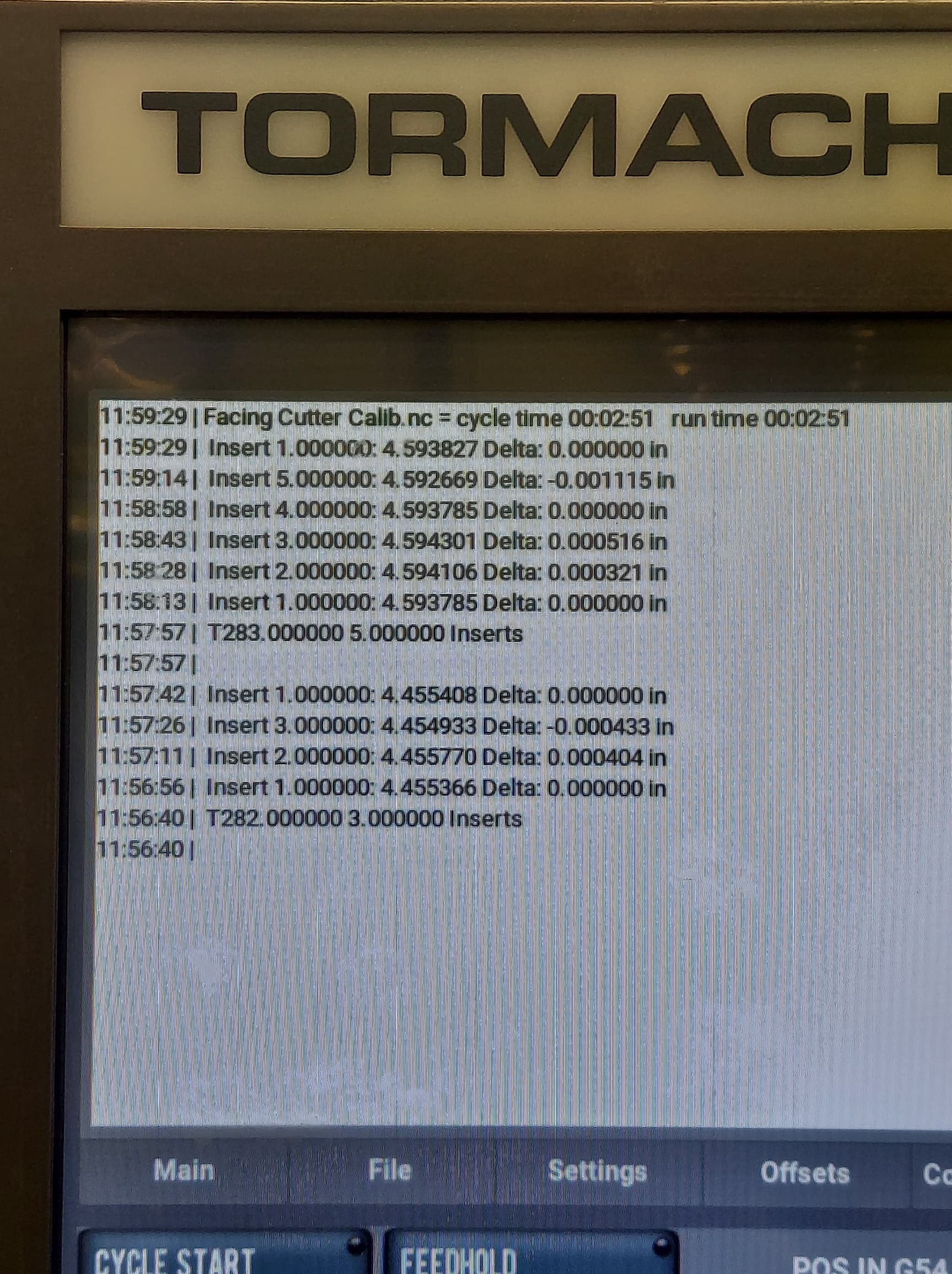
The results are shown in the following screenshot. You can see from the screen shot that all 8 inserts are evaluated in under 3 minutes and insert #5 on the 3" cutter shows wear upon inspection.

1 Like