I am having bizarre runout issues. I have attached a link to the video. Basically the Bt30 tool holder has almost 0 runout then I release the tool holder and turn the spindle or tool holder half way around and put it back in. Then I get about 10um of runout. Repeat and their runout is gone. Change tool holder (different brand) same result. I can’t even beggin to guess what is causing this. I have cleaned all collets, tool holders , the taper and even the belt. I have tried 3 different brands of tool holder with same results. The spindle is new <20 hours on it. The whole mill is only a few months old. Anyone have any ideas?
No I can’t just mark all the tool holders and use them on the 0 runout side because sometimes both sides have the 10um runout.
@Dr_Harold_Jones while I wasn’t able to watch your video or see what’s going on, the thumbnail shows that you are using ER tool holders? If that is the case, the collet itself is probably where the runout is coming from. What I would recommend doing is taking the tool and collet out of the holder and measure the inside of the tool holder where the ER would normally reference against.
Here is a great video by John Saunders did talking about runout and showing you how to “dial in” an ER tool holder.
Where are you measuring to?
I would start at the inside taper of the spindle and work my way out. Then the collet taper in the holder. Use a gauge pin in the collet. Be sure to check vertical alignment first. If that’s bad, everything else is crap.
Also if you’re looking for 10ths accuracy, you really need 100 thou scale.
Some do and some don’t, but i like a very thin coat of oil in mating surfaces, helps things seat. Not the mill itself though.
+1 on what Bruce Keller said, tho I would think the shank of a carbide end mill is pretty accurate. So out of curiosity I tried a few things, straight off my tool rack, no Saunders ‘tapping things true’:
empty BT3- spindle bore <= 1 micron
tool shank in Maritool SK10 holder: ~ 1-2 microns
tool in Maritool ER-16 with Tecknics DNA ‘dead nuts accurate’ collet: <= 1 micron
tool in regular ER-16 collet: ~8-9 microns!
The issue here is that I a measuring the tool runout as 1 micron and then simply pressing the drawbar release, rotating the tool holder 180 and putting the tool holder back in the spindle. Then the runout is 10 microns. If I repeat the above on the same tool holder or pick another tool holder it goes back to 1 micron.
Video
Runout mystery
Sorry, been out the loop.
Inspect all holder surfaces for witnesses marks, ie not symmetric. Check the pull stud, tight and seated completely. Ah, use a mirror and flashlight and check the pull mechanism in the spindle ( can’t remember proper term) and lube it. Think antisieze is recommended. Maybe the collet is sprung?
Done all that. This is a machine that was installed in march and the spindle was replaced in June. I am refreshing the video link. I know it’s long but it really shows how strange this is. I have almost 0 runout and then when I remove the tool holder rotate it 180 degrees and reinsert it I have loads of runout. Do the same again (with the same tool holder or a different one and it goes back to 0 +/- . It has to be something in the spindle that only affects one side of a cylindrical surface across multiple brands of tool holders and pull studs. I might send in a ticket. My brain just can’t comprehend how a symmetrical circular mount can be centred in one arrangement and wobble in another.
Ok, first thing I noticed was that your indicator lever should be around 15 deg to the surface. That will give you most accurate reading. Kinda looks like it was pushing on it funny.
I tried a old 3/8" edge finder body in a ER20 collet, snugged it in my hand with a crescent wrench. Had about 0.0025" runout. Went 180 deg and got about the same using a 10ths indicator.
Loosened it, put it in the tightening fixture and torqued it to 45 ft lbs. Runout dropped to less than 0.001".
Then I used the shank of a carbide tool. About 0.0007 runout. Not bad for just throwing it in there. Nothing close to what you are getting.
Maritool sells a torque wrench and adapters for torqueing collet nuts and pull studs. Had to modify one to torque the ER20-M nut but can use it on the ER20-A nut also.
I torque everything so I know I’m doing the same thing every time. Very small drill bits and endmills etc under 1/8" I tend to do by hand because it’s easy to over torque the nut and collet. But everything else I torque. Also measure up closer to the collet, tool quality isn’t what it used to be.
Make sure the indicator is sitting at the correct angle so you are getting a true runout and try torqueing. A thin coat of oil on the collet taper and nut threads, not the tool itself. But remember, oil can increase torque up to around 10%.
See what that does for you.
Nice drill chuck by the way!
Any luck figuring out the runout issue?
Living with it for now. It’s definitely something weird. Measured inside the spindle bore and it was +/- .0004mm (quite impressive.) I am using high precision .002mm runout tool holders with .005mm high precision collets. So with all that the runout is repeatable to +/- .0002 mm. I guess some of the .002 and .005 cancel each other out? But when I take out the tool holder and rotate the spindle 180 degrees the runout goes up to .012. The weird thing is that if I then take the tool holder apart and put it back together the runout will be the same as the first test. This is the part that baffles me. I could understand if the runout changed a little like 0deg was .005 and 180deg was .009mm. That would make sense but every time 0deg is .000 and 180deg is .012. Different size tools, different tool holder brands, even 10 micron runout collets give almost exactly the same runout. I’ll try uploading the video again.
Did you install the spindle?
It comes as an assembly right so should be pretty much R & R.
So maybe a bad spindle?
Check end play on bottom of spindle? No holder, just actuate the draw bar. Then holder in / out? That might tell you if the spindle shaft is moving up and down. If the bearing nut isn’t tight / torqued properly, the bearings may be being pull out of alignment. Or they aren’t fitting properly in the bore. Any noticeable difference in the way the bearings feel with or without tool holder? Probably pretty hard to tell. Torqueing that nut requires black magic and voodoo so unless its loose or you have other indications I wouldn’t mess with it.
If the spindle taper runout is good, and various manufacturer holders are good, something in the drawbar assembly is pulling it out of alignment.
Look at the parts diagram, page 226.
Hate to say it but you probably need to pull the spindle out and check everything. Or at a minimum the drawbar and the clamping unit. Sometimes I forget but I try to have a tool holder in place when blowing chips so as not to get any up into the spindle and clamping fingers. One of those could be bent, but I would think it would still pull up into the taper ok. Could be wrong. Sometimes it doesn’t take much. Bellville washers nut crushed or bent. Use a mirror and flashlight to look at the clamping fingers. Something obviously bent or off center. Hook and rag to clean the upper inside of the fingers. Pull out any evidence?
Open the cover and actuate the power drawbar and just watch it. From underneath too.
Grab the drawbar and shake it best you can. Feel anything? Same with the spindle and a tool holder. Not going to hurt anything. Sometimes you get lucky and something clicks or snaps into place. Or just wobbles around.
Check the bolts on the underside of the power drawbar under the long round bars - tight. Mine loosened up in shipping. I don’t like the single spring - bolt and guide pin arrangement. Pretty clunky. I put a slightly larger pin in to guide a little better. Eventually I’ll put a another bolt and spring.
Look for fretting, signs are black oily residue and witness marks, burrs.
I’ve worked on Naval aircraft and engines for 20 yrs and aerospace composites with engineers for 15 yrs.
Keep hunting Doc, it’s there, just have to find it.
Actually this is my second spindle. Tormach warranty’d the first one because after 10,000rpm runs the holder was locking into the taper.
Story of trthe spindle warranty replacement. - [the tool holder would swell enough that it could only be ejected after a 10 min cooldown if I cranked the drawbar psi up to 110psi, at that pressure the holder would eject so hard i was afraid my wrist would break from the eject force. They didn’t tell me the reason for replacement but the spindle temp was measured at 129 degrees F so I assume I had a bad bearing.]
I installed the new spindle assembly and reinstalled the power drawbar, encoder, etc. I did notice that some of the spindle cartridge bolts holding the spindle to the casting were very loose during disassembly. I made sure to torque everything to spec. I did my best with the drawbar install as there isn’t much info on the tormach system.
I do use a washer under the foot of the locking pin side of the drawbar holder. Could that throw it off? The other side has a spring on the bolt.
Power drawbar piston reacts against the lower plate like pliers, so once everything is released, the lower plate should not contact the spindle. So if the washer is lifting the plate and it is touching then it’s no good.
I’ve been told that torqueing bearing nuts on spindles can be done by temperature. Brought up to speed and measure operating temps. Like I said, voodoo.
I’m running 105psi on the drawbar. I think that was recommended pressure. Just enough to compress the Bellville washers. They do the actual clamping when released. Turn down the pressure if you don’t need it. Just have to release the holder.
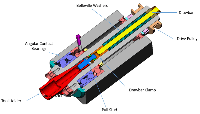
For the basic idea, the picture shows the bearings etc. All the tool holding tension occurs with in the spindle.
Follow the path, tool holder, tapered spindle, inner races on the 3 load carrying bearings to maybe a shoulder and a nut. (Don’t know exact arrangement in the Tormach spindle) Then the upper bearing.
So during a tool change, all the force from the power drawbar pushes down on the spindle shaft. Install a holder and the Bellville springs push it back up.
If the inner races are not secure, they could be getting jacked around, but that would cause higher operating temps for the bearings.
The tool holder and draw bar are all internal to the spindle shaft. So the only thing I can see is the drawbar or clamping unit is bent or damaged. Still doesn’t quite explain the 180 degree in out thing.
Have the cartridge bolts loosened at all? If the bolts are sloppy, try new ones and or blue Loctite.
I would ask Tormach for help and or another spindle. You shouldn’t have to put up with that much trouble. High spindle speeds require a pretty good safety margin. Last thing you want is a holder to fall out at speed. I wouldn’t work on the assembly though without direction from Tormach.
It’s all happening in the spindle shaft so maybe another bad spindle? Stuff happens.
A lot of info.
Did the video link work?
I will work through the info and see if I can update tomorrow.
The thing that throws me is the non linear exception to circular geometry. ( the spindle taper geometry is way, way in spec.) I just looked and realized the pull stud taper clamps are locked to the spindle so any anomaly to blueprint specification would translate to axial clamping irregularity.
Can you give me some info on the pull stud teeth? Is the clamping geometry axial or taper centric?
Didn’t see a link.
Not sure exactly what you saying with the pull stud but it should be concentric with the holder and both axes aligned.
Speaking of, are you using Tormach studs?
I use them no matter the holder manufacturer and have had no problems. Theoretically any that meet the size and spec should work.
90psi min for air pressure to draw bar.

Here is a spindle rebuild. Easy peasy. Seems the drawbar itself comes right out the bottom. Not much detail on the removal but you can buy the clamping unit from Tormach. Just make sure the Bellville’s are facing the proper direction.
You could pull it out and do a better job of inspecting it.
Seems this guy had bearing problems too. Bearing alignment marks on the inner and outer race must be lined up for matched bearing pairs. FYI
Asked my buddy about this.
Look at your tool holder where the notches are that engage the lugs on the spindle.
Is there a mark, laser engraved circle or otherwise on one side?
If so, these holders need to be indexed. The holder is designed for a longer drive lug on one side. Check the depth clearance between the lug and the notch in the tool holder. If it is hitting on one side (side with the mark?) then you’ll have to index it to the other side. And it probably won’t be much. Or replace the tool holders. That would explain the 180 deg. out issue.
My tool holders have writing all over them. I don’t think they are indexable but I have put in a call to cutwel (my tooling supplier in there uk). Here are the 3 I use most.
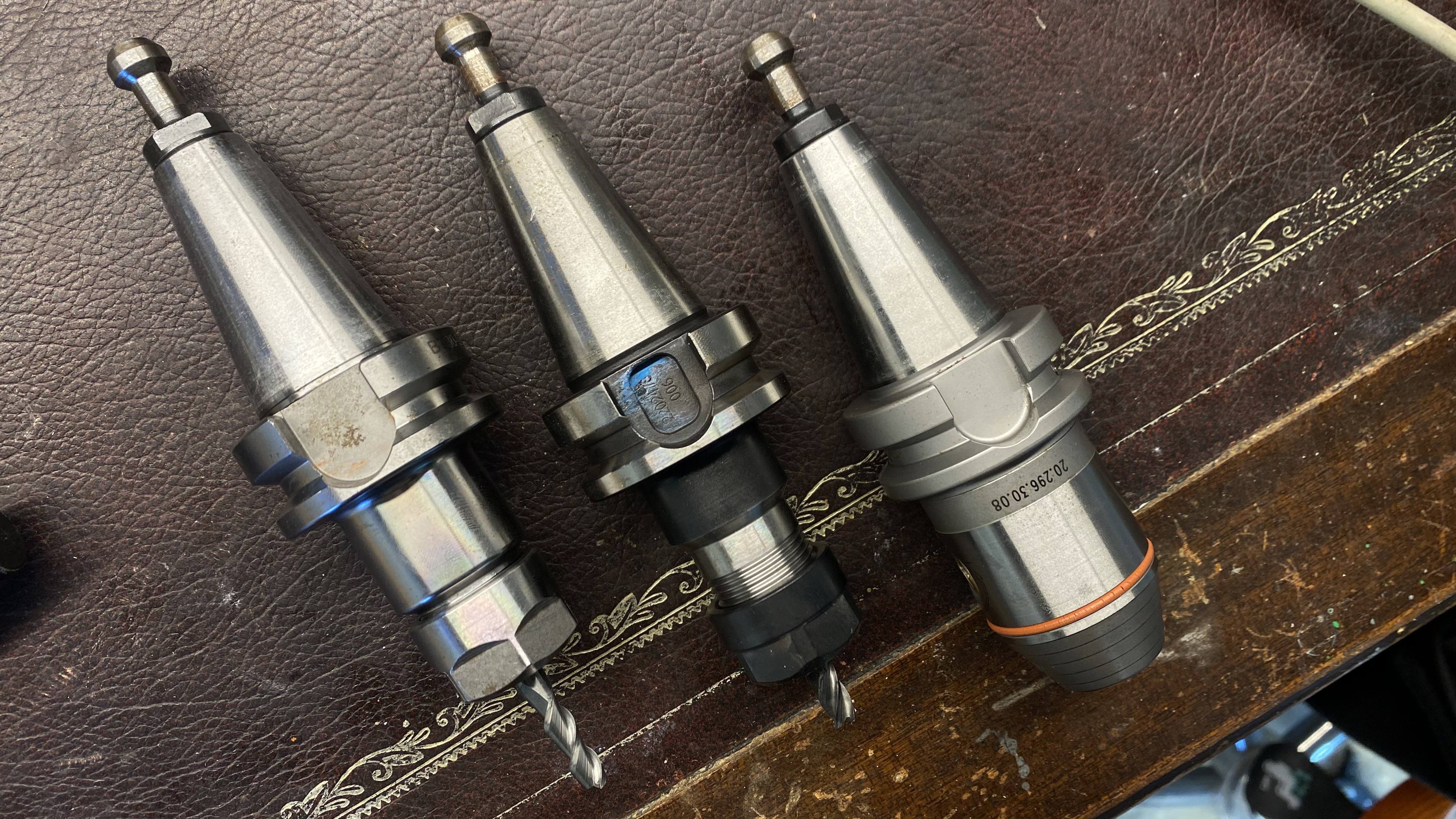
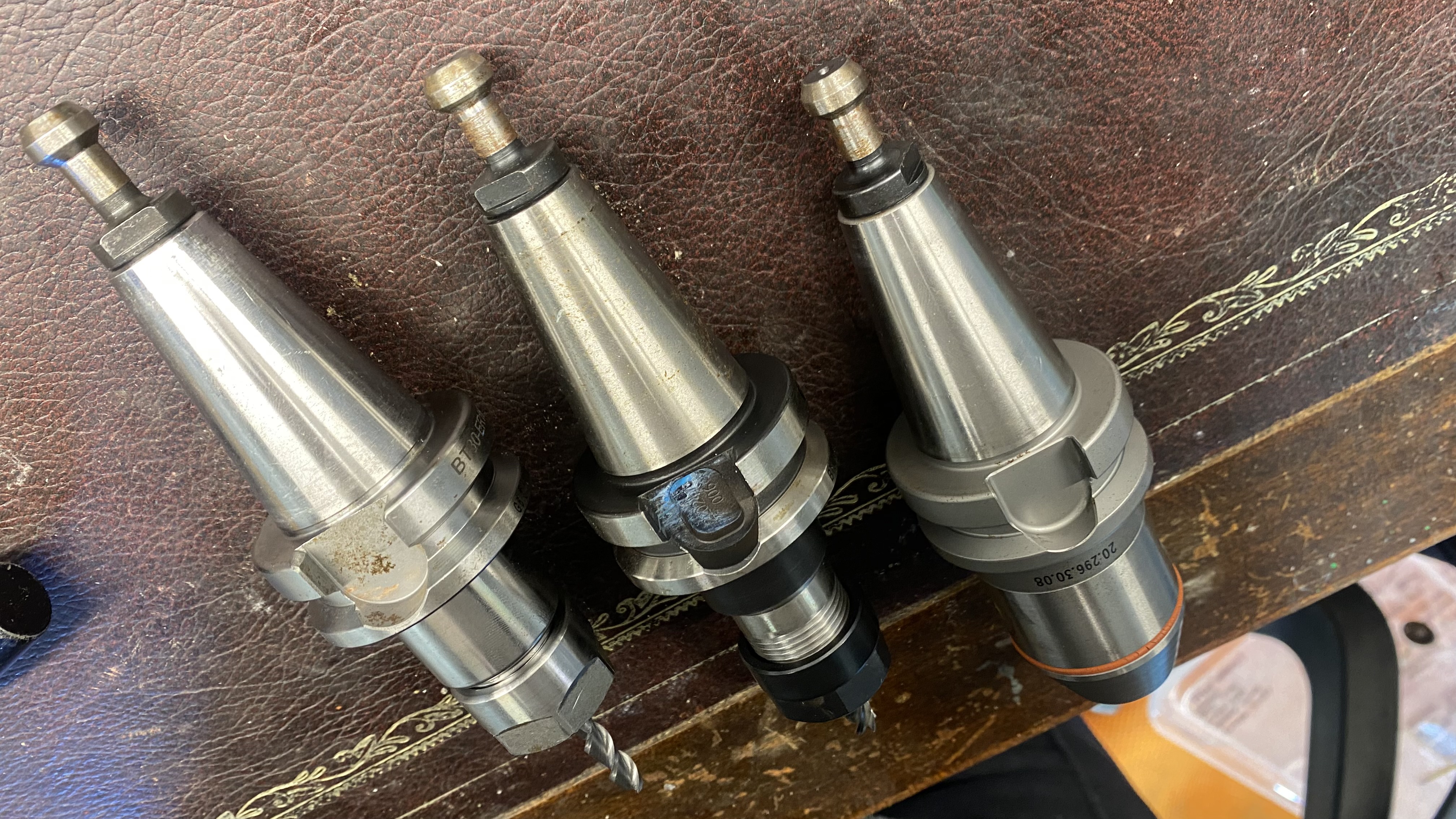
All the pull studs are cutwel brand as well. I have a tormach pull stud on my probe I will swap into one of the tool holders.
Are you in the United States?
I buy Tormach holders and studs, relatively inexpensive, quality seems to be there and should mate up without issues.
Measure lugs, holders, width and depth. Then a good visual with a flashlight.
Something is bothering the spindle.
Wow so many things developed over the last year. It’s is still an issue with no apparent solution. Some have said that this problem is actually impossible. I am starting to think it is a flaw in a bearing because it is only detectable when the spindle is warm. When the spindle is cold the runout is about .09mm on both orientations of the tool holder in the spindle. Once it is warmed up the runout is .001 in orientation A and .015 in orientation B. (average across 3 tool holders. Need to measure the bore warm and cold.