I’m not certain the new path pilot version is to blame here but I’m having an issue with probing.
I use the xoomSpeed post processor thanks to its probing support (Fusion 360) to update work co-ordinates after I power up the machine. Even though it’s an MX machine I get 1-3 thousands offset after power on.
Basically I have 12 parts in a fixture each with its own WCS. The probing routing hits all the parts and updates these locations. This has worked perfectly until I updated path pilot. (I do have the most recent release installed)
I’m using Fusion 360 probing routing which starts with moving the probe over the part and it plunges (Z) then starts it’s probing routing.
When the routing switches from it’s fast move to probing I get a “Unexpected Contact with part error”.
I’ve slowed the machine to as slow as I can move it and the error still occurs at the same spot. I raised the distance from the part where it makes that transition and the error follows the new location.
The pathpilot console built in probing routinga run with ZERO issues. Watching the led on screen never shows the probe actually tripping.
As a final test I physically removed the probe from the machine (still plugged in) just not in the spindle and the error still occurs same place.
This feels to me like a variable isn’t initialized correctly and the instant the probing routing looks for a signal it’s getting tripped.
Normally in these types of situations having the wrong type of probe selected would be a suspect, but since you are able to do rapid moves and the standard probing routines work fine that would be ruled out. I would recommend reaching out to David Loomes, maybe there is an error in his macros or his post or some other weird thing going on.
Eric
I run my 1100mx the same way with multiple parts and different WCS with in-process probing using David’s post
running parts right now
no problems at all
Ed
kinda strange - I’m betting it’s something simple though
Out of curiousity, have you tried reverting to an earlier pp version to see if the issue persists or goes away?
As a separate thought, since the error only occurs with the Fusion posted code, and follows the location of the feedrate change, do you have some kind of tolerance built into the probing routine in fusion? I haven’t used it myself so I don’t know if that’s even an option but if, perhaps, you gave it a very small (or maybe zero, or negative?) tolerance between where it’s expected to make contact, and where that contact actually happens, that might be causing the fault.
Well still chasing this down. When the machine is turned on from cold shutdown the probing routing works for the first part probed then the error trips on the second part.
Resetting the program and running it again will cause the error every-time after that.
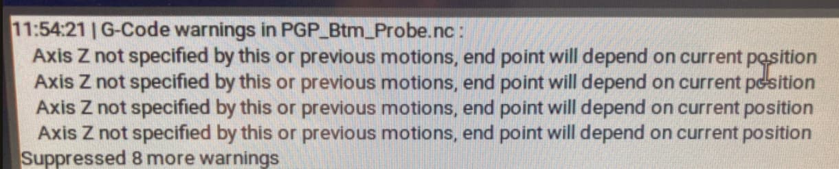
I’m also getting an warning I’m trying to understand now when importing my fusion code… I’m not sure if they’re related but they might be.
The Z for each WCS is set once in the work offset page in pathpilot. The base of jig that’s holding the stock isn’t variable like the length of my stock so I use it as my datum for Z in this first step.
The jig clamps can move the stock around a little bit usually +/- .004 " or so and I use the X/Y probing routing to lock down the center of the stock to correct for that.
Eric
Maybe run a test on a sample program and insert a Z probe routine before the X Y routine to see what happens
just for trouble shooting - if that works - maybe David can work around it
Ed
** Switching from a “partial circular boss” probe routine in fusion to a full circular boss took care of the warning messages **
The XY circular boss probing function is working properly. Using the “XY circular partial boss” option is not working and causes the unexpected contact error and associated warning messages.
New here and to this machine, probe system and fusion so keep that in mind!
Despite this being an old thread I am hoping someone might swing by,
I’m having a similar issue that may warrant the creation of another thread but was hoping if I shared it here I might gain additional clarity. On to the issue:
My probing operation from Fusion seemingly operates correctly and updates my WCS accordingly however it is in fact Not in the center of the bore, despite the controller re-zeroing in X/Y ??
The controller/path pilot probing routines all work consistently without issue, only when I output from Fusion do I see this issue. I have chased it around in Fusion such as the ‘override driving WCS’ despite only working in the singular G54 (it informs me it will do nothing lol)
If you are using the standard Fusion post I’d recommend opening a support ticket for us to look into. If you are using the Xoomspeed post I’d recommend contacting David Loomes.
I have also been working with this as well. I found that the Fusion will switch to a work coordinate over ride in the post but there is no way to tell it to set the location X0 Y0 Z0 for the WCS override. Fusion sets the X set and Y set values equal with the primary driving WCS. You have to edit in the posted file to set the locations for the WCS override.
John, “WCS Override” as Fusion defines it for WCS probing doesn’t have anything to do with the actions it takes after probing. It is just where you define which WCS to use to drive the probe’s tool path if you don’t want to use the same WCS that you will be updating the origin for when probing. Otherwise the WCS that drives the probe toolpath and the WCS you update the origin of based on the probing will be the same - whatever you set as the WCS in the “Setup” (you can change the active WCS for a subset of toolpaths by putting them in a folder and changing the WCS for the folder in its settings - this is how you would probe to update multiple WCSs in one setup without needing to probe immediately before each WCS is to be used). You can use WCS override to drive all your probe toolpaths from G54, for example, which doesn’t get updated in the program, so if a WCS origin hasn’t been established yet the probe won’t be moving relative to a random WCS origin that you may have left over from a program a long time ago or still be defined as 0,0,0 relative to machine coordinates. So you’d only need to manually update G54 to match your program and then the probe routines will do the other WCSs. In that sense, it’s safer to use WCS override because you might forget to set the rough origin position of all the WCSs that will be updated during the routines.
And a reminder for anyone confused - the Fusion WCS probing routines do not set the point/center that you probe to be 0,0,0 after probing… unless you defined that same point/center as the WCS origin in Setup. If not, it probes some other point and then shifts the origin by some amount such that the origin is located in the same relative position to that point as it is in CAD. So it’s usually good practice and less confusing to just set your WCS as the same point/center you probe if possible.
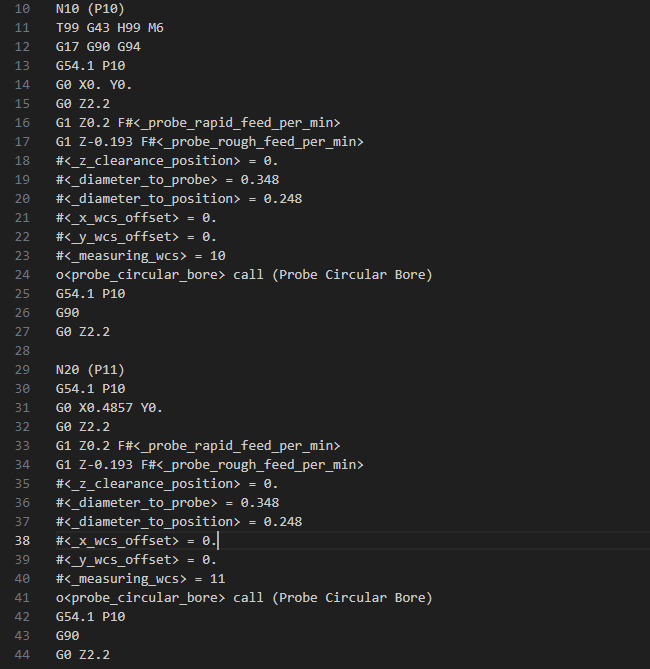
Below is what I was trying to accomplish. Using the G54.1 P10 as the driving coordinate system and set the probe position. Once at position <_measuring_wcs> gets updated along with <_x_wcs_offset> and <_y_wcs_offset>. After the probe routine is finished the system resets back to the driving G54.1 P10 to continue.
The ticket I opened with Norman concluded that you cant set multiple WCS at the same time.
My use case would help setting up multiple WCS on fixtures with multiple parts.
Set G54.1 P10 active
Drive the probe tool path with G54.1 and probe a circular bore located at 0,0,0 relative to G54.1 P10
Update the G54.1 P10 origin to match the center point it probed.
Set G54.1 P10 active again
Drive the probe tool path with G54.1 and probe a circular bore located at 0,0,0 relative to G54.1 P10 again (though it’ll use the updated origin from the previous probing op)
Update the G54.1 P11 origin to match the center point it probed.
Set G54.1 P10 active again
So the result is that your G54.1 P10 and G54.1 P11 WCS origins will be almost exactly the same point - you can verify this relative to machine home/reference position in the work offsets page.
Not sure what Norman means by “you can’t set multiple work offsets at the same time”, but the code excerpt I post below is an example where it uses G54 to drive the probe to update the Z origin of 3 different WCSs one after another. Then it does a tool change and machines the same toolpaths in each different WCS, but the XYZ coordinates are different because each WCS has the same origin defined in Fusion (they all have the same origin as G54), so it needs to go to different locations to machine each part in each coordinate system. It does a G30 retract between the operations for each folder, but for the probing operations I had to add a G30 as pass through NC after each operation or folder because for whatever reason Fusion didn’t automatically generate a retract.
I use this as part of a full program to cut multiples of one part in the same fixture with known spacing between each stock. I could also update X and Y origins to get more accurate centering of the toolpaths on each stock but in this case that wasn’t necessary, I just needed accurate heights relative to each stock. Not sure if this is what you’re trying to do, but it works well.
To generate it in Fusion I used G54 as the setup origin and DON’T select “multiple WCSs”. For each probing operation I select "the “override WCS” as G54 and then put each operation in a different folder and set the WCS for each folder to be whatever WCS I want the probing op in that folder to update. Then after all the probing operations are done I set up the cutting tool paths and put those in separate folders each with the appropriate WCS set - so the tool paths for G54.1 P29 are all on the same part that was probed to update the G54.1 P29 WCS origin. Then the cutting operations for the next part are in a folder with G54.1 P30 active and so on. It’s all in the same setup, and post processed with Tormach’s latest post (although David’s post treats it the same way).
Line 31 moves the probe for the second hole while in G54.1 P10.
If your code works, then the issue could be inside the “o<probe_circular_bore>”. When ran, the program completes the set of G54.1 P10 and sets it X0Y0. Probe retracts and goes to the second hole location then to probe depth. The probe operation starts but after its first roughing contact it travels back towards the G54.1 P10 location. Contacting out and stopping the cycle.
I also was playing around with the folders forced WCS. Made my head itch.
Whoops, I missed line 31, yes it’s a second bore and a different location for G54.1 P11.
Yeah it sounds like your issue might be in the circular bore subroutine… you can try reducing the approach amount and widening the size/position tolerances. Check that the diameter of your probe tip in Fusion matches your actual probe and is close to the effective diameter set for T99. If that doesn’t work, maybe try doing two Z- probes instead of two circular bores to see if your setup works with the same subroutines mine uses. If it does, then I can take a look at the circular bore subroutine and see if there’s an error or if it can be modified to be more robust.
Or just send me or post here your fusion project file and I can take a look at how it’s set up (though I’m on vacation so I won’t have access to fusion until May 31). Make sure “Multiple WCS” is unchecked in the setup and/or wherever it shows up… I remember trying to see what it did and can’t remember how it worked but it didn’t do what I wanted it to. Well, I have to double check that I have it un checked, but I’m 90% certain it is.
I guess an alternative to the folders would be to have multiple setups, one for each WCS as defined in the Setup “Post Processor” tab. You could define a different origin point for each if needed for whatever reason (I use the same origin for all WCSs to keep things simple, and I don’t think it’s possible to have different origin points with the folder method). Just select all the setups when you post-process so you get a single program.