Question about the pneumatic cylinder. I am guessing that the 3 extend ports along the length are because it has multiple pistons in the cylinder? 2 of the retract ports (I am only guessing what those are) are not hooked up. Only the retract port at the bottom of the cylinder has air plumbed to it. The 2 higher retract ports are open. The issue I am having sometimes is that when I press the pushbutton to extend (and release a tool) air blasts out of the upper return port right at the end of travel. When this happens you can see the top of what appears to be the pistons passing the opening of the orifice, creating a gap for the air to escape from. Most of the time the tool releases. Should this be happening? Do I need to adjust something like reduce the travel of the cylinder? The cylinder is mounted on its shoulder bolt; with the qr pin on the other side, and floats vertically like it is supposed to. One thing I notice is that the large hex bolt on the cylinder shaft is not centered with respect to the drawbar. When I pull the qr pin out and rotate the cylinder to roughly center it over the drawbar the system works without any leaks. But I need the qr pin installed to prevent the thing from rotating on its own over time. . Is the piston rod supposed to NOT be centered over the drawbar? Thanks
Yes, it is a 3 stage cylinder and that’s why it has so many ports. The retract function doesn’t have to overcome anything other than internal piston seal friction which is why only one stage is used and the remaining ports are left open.
It definitely sounds like you have an overtravel situation going on but the bolt not being centered over the drawbar sounds suspect. Are you using the correct hole for the QR pin? Is the round cutout in the cylinder base plate centered around the spindle collar?
If you’re able to post some pictures, that might be helpful
@Ian_Vivero I spoke to @jwallner at Tormach about these ports once, and porting the exhaust ports back into the opposite side port (I think) as a result, the air tool oil gets contained. Have you heard of this? What’s your take? I keep meaning to check back with John on that, but haven’t gotten back to it.
I’d have to see a diagram of what you’re talking about to really understand what’s going on and how it would work. On a very basic level, sure, the oil wouldn’t be blown out into the open air as one side or the other exhausts, but I’m not sure that’s a significant advantage as there isn’t a whole lot of oil being consumed with each cycle of the cylinder. And since the exhaust is run through a filter (typically anyway) I would expect most of the oil that does get blown out to get captured in that brass mesh and ultimately just drip out and combine with the rest of the tramp oil in your coolant.
Thanks for the response. I’m using the machine right now but over the weekend I will post a picture. One thing- the machine is blowing out primarily air. And when I manually position the cylinder shaft concentric with the drawbar centerline it doesn’t leak. Maybe an assembly error? But the locking pin does not line up with the mating hole in the casting when the cylinder shaft and drawbar shaft are eyeball-concentric.
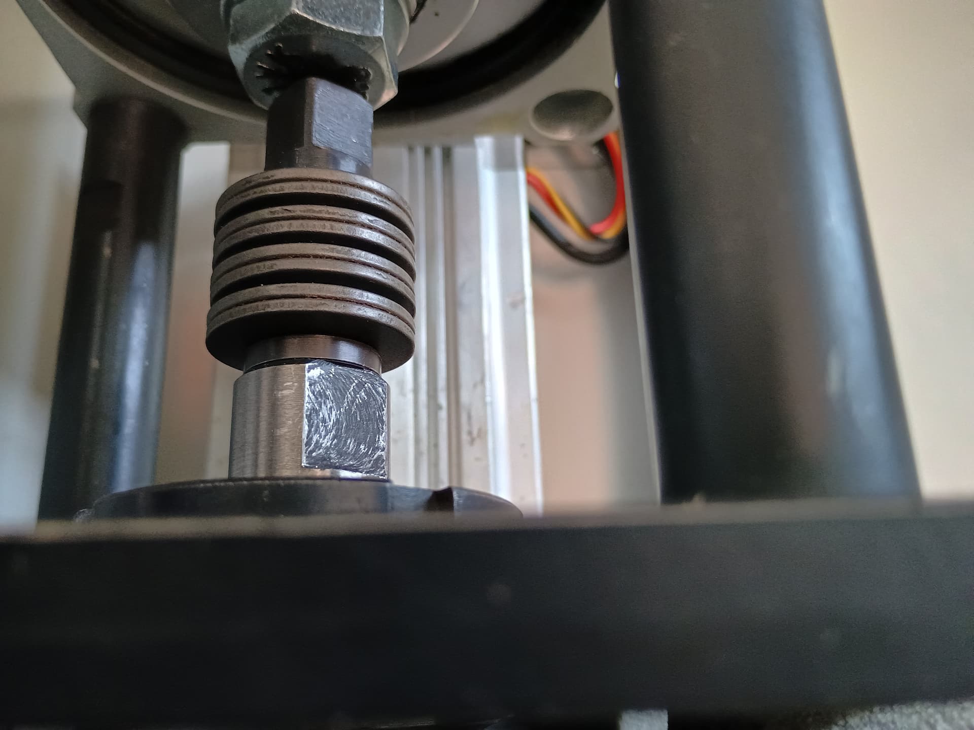
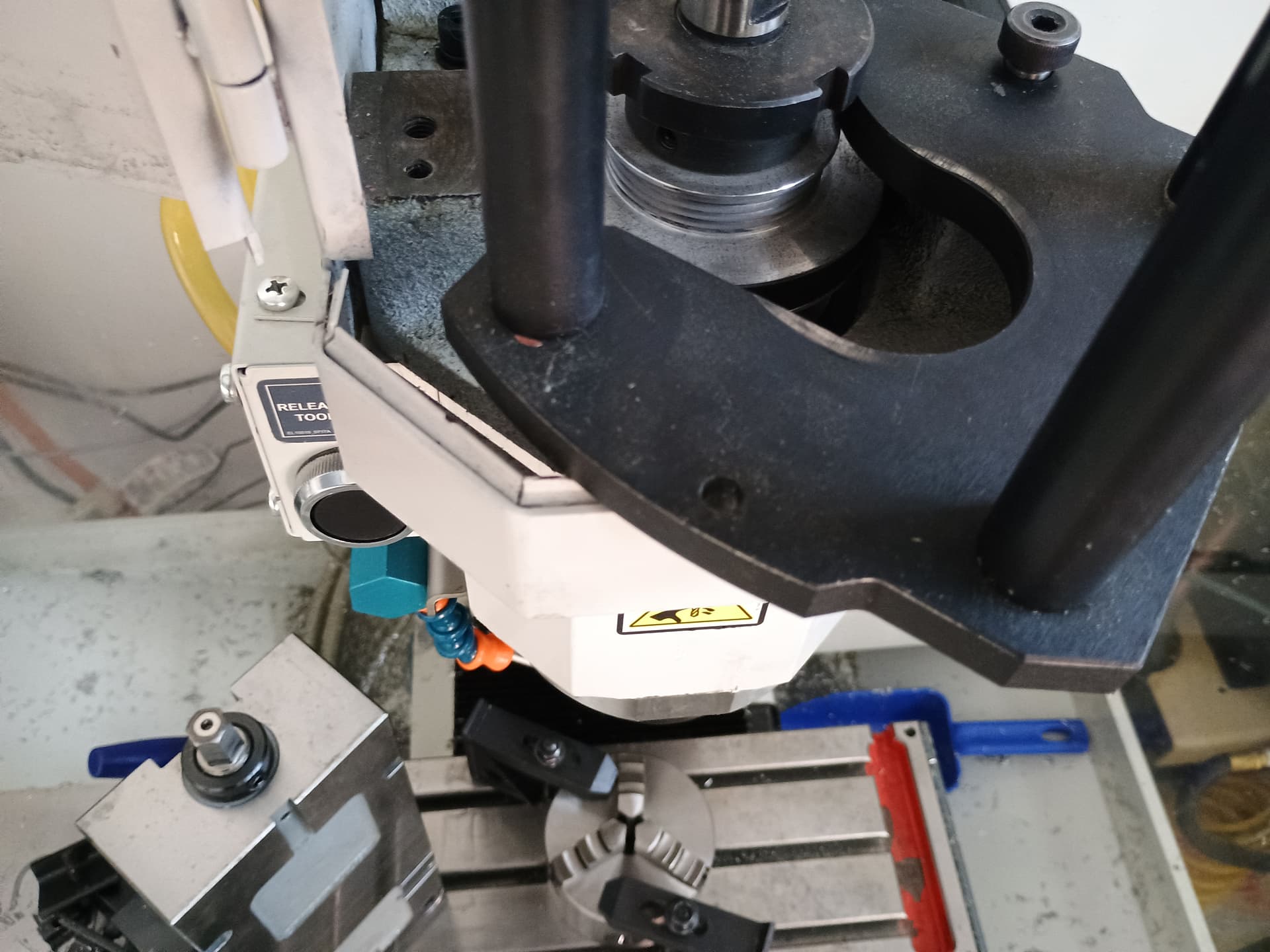
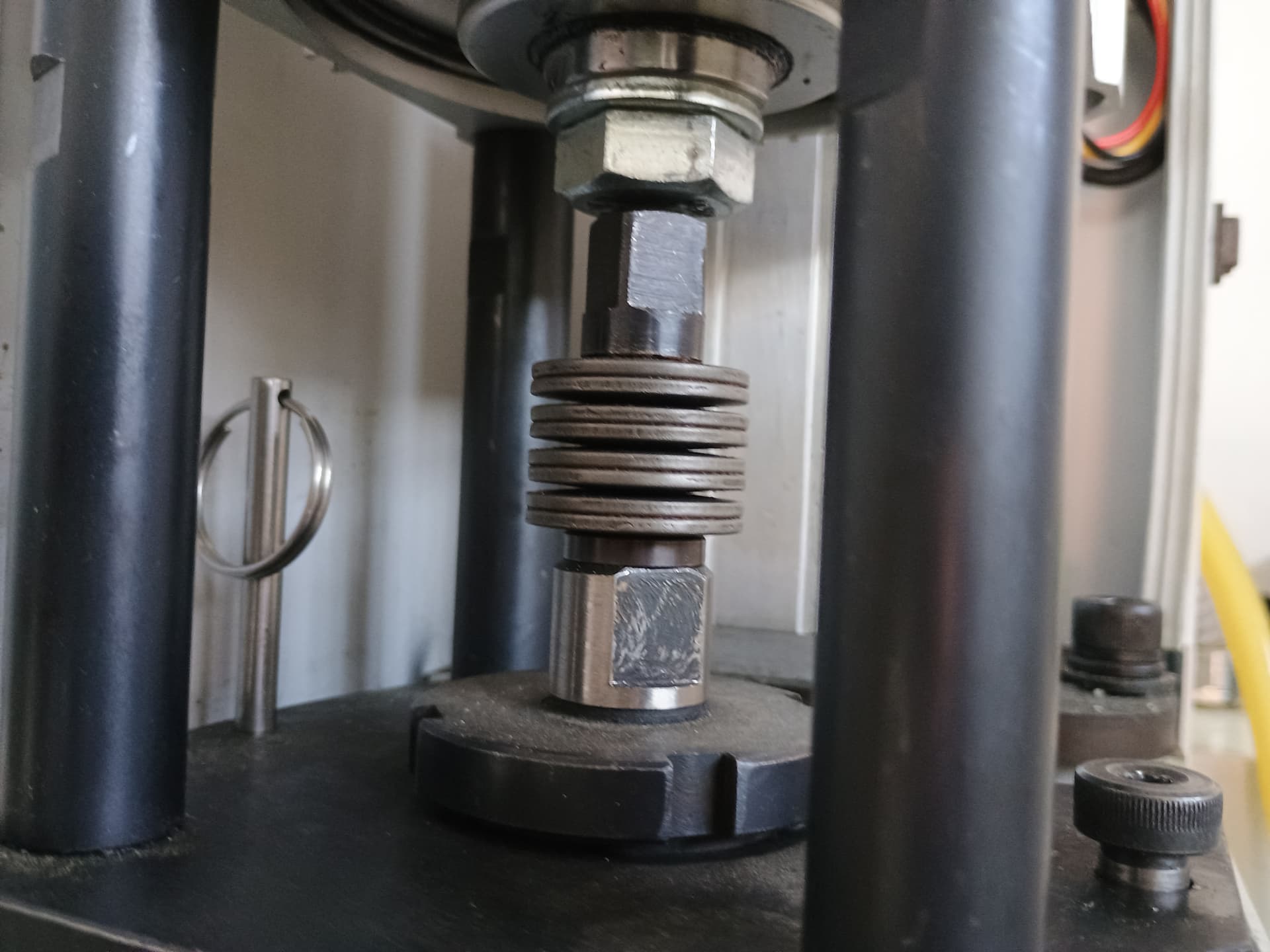
Here is a photo of how the drawbar axis is misaligned with the center of the cylinder. This is with the QR pin inserted thru both the black plate and the hole in the casting.
If I pull the QR pin out and rotate the cylinder about the shoulder bolt to align these axes, the air leakage does not happen. But then the cylinder floats not only vertically, but also rotationally about the shoulder bolt.
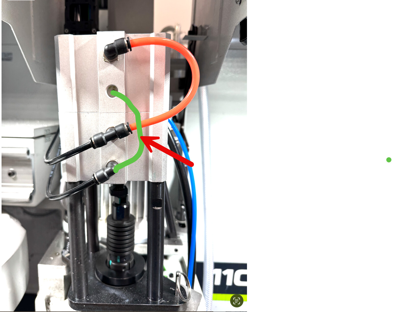
@Ian_Vivero here’s a diagram of what I was talking about. I believe this is what @jwallner was talking about but it was when I first got the machine and I had all I could do to get the basics of the machine figured out. The green line I drew in would tee into the bottom port and then connect to the open port of the top stage.
@Drew_Miller that amount of misalignment wouldn’t normally concern me except that you’re saying if it’s corrected, the air leak doesnt happen which I find odd and can’t explain. Hard to tell from the picture but perhaps you have too much gap between the bolt head and the drawbar allowing the cylinder to overtravel? Even that seams odd though as I would expect the cylinder to be internally limited to prevent that kind of thing from happening.
Are you the original owner of the cylinder and have you rebuilt it at some point? I’m wondering if one of the internal rubber washers is missing. Just rebuilt the cylinder on my 440 and there are thick rubber washers on both sides of the pistons. Presumably as end stop dampers but potentially also function as travel limiters.
@Scott_Dube yeah I don’t see how that could cause any issues. It would increase the pressure applied to the retract motion which doesn’t require any real pressure but it’s nothing the cylinder isn’t built to handle.
It’s working fine now that it’s centered but the qr pin doesn’t line up with the mating hole. I am the original owner and the cylinder hasn’t been taken apart or anything.
Looking at my casting there are 2 holes; one’s larger than the other. Neither align when the cylinder is on center and the qr pin only fits the larger hole. I think this could be taken care of if I can modify the floating plate with a hole that lines up. Is there a drawing of the part I could look at to see a)if the hole is in the right place and b)to use to make the change and put the hole in?
Regarding a leak when it’s off center; if the cylinder is pushing with for example 1000lbf, and it’s skewed, it’s conceivable (not likely) that there is a force component lateral to the cylinder axis or even some weird bending that could overcompress a rubber seal on the opposite side of the cylinder, allowing air to find a way out. Seems far fetched but something is happening. I don’t think it’s overtravel; because when it’s centered everything stays airtight. If it is overtravel, it’s probably slight and also related to the fact that it’s off center and might be moving a slight amount more due to a more “glancing” contact with the drawbar.
Any ideas on where I can get a drawing of the floating plate? Thanks Scott and Ian for you ideas and troubleshooting help especially given my sketchy description.
With multi position pneumatic cylinders a lot of times the “return” stroke is NOT multi-position so you really don’t need the port “returned” and you really shouldn’t see much lubricated air coming out of this breather port. Though not necessary, I am installing 2pc (my draw bar has 6 1/4" NPT ports) of a muffler in the empty breather ports to keep crap from getting into the cylinder. The oil leaking from the lubricated air out of the valve exhaust ports (1/8" NPT sintered bronze muffler)can be captured as a few companies make what is called a re-classifer muffler and this is where you would run the two exhaust ports from the tool changer or single valve into. I plan on installing metal fittings as they will hold up better to “mistakes” as our unit is in a high school and I can see a lot of upcoming issues with the cheap plastic ones provided. I am also changing the air prep out to a higher quality more robust unit from Festo or similar.
In this thread, Drew was talking about his PDB having 3 cylinders and the over stroking issue. Down in the thread I see Scott posted a picture of a PDB on his 1100 and it has a two cylinder PDB setup. I purchased a PDB setup used off ebay that showed a 3 cyl setup and a two cyl setup came in the mail. I had ordered a rebuild seal kit from Tormach to fix it up. The diameter of the cylinder bores appear to be the same so Im thinking it will be fine. My question is really this, did early Tormach mills have a 2 cyl PDB setup as opposed to newer ones that are using a 3 cyl setup? Tormach spare parts only sells the rebuild kit for the 3 cyl version, (my kit is still in the mail)
Im planning on using the PDB setup from the 440 mill on my G0704 mill.
I know the early 1100 PDBs had only two stack cylinders because I had one. The 2 worked fine for me for years, but I heard it could be marginal with lower air pressure and people wanting a tight bellville stack so they changed to the 3.
Yeah, BT30 is a different thing for retention with pull studs and a taper and drive lugs so it might not be needed. My M-converted-to-MX-by Zbot has a triple cylinder and works fine FWIW.
I’ve got a triple cylinder MX converted M as well. It works fine, now. But I had to shim the cylinder to remove a bunch of the free movement before it engaged with the drawbar. Prior to that it would release some tool holders, sometimes, but I had quiet a few that would not release without prybar assistance. After shimming I only have two toolholders that ever give me grief but it’s usually not too bad.