i am new, some of my lingo/terms are going to be wrong hopefully this is understandable enough
is there a way to have the constraints/measurements on my cad drawings from freecad or autodesk hobby match the inputs that path pilot wants to append tool paths to the gcode files i have created with CAD. then i can just read the drawings and input all those x, y coordinate information to generate tool paths/ build cutting profiles on path pilot
i am trying to see if we can do our lathe machine work in house. obviously trying to start from zero without a mentor and an actual piece of equipment is challenging, so i am trying to gather information as we go.
i have learned with autodesk hobby version and freecad how to make drawings of our part profiles and create 3d solids from the sketches.
neither program has lathe support for CAM. but i did learn how to start a CAM profile(job) and the export the file as gcode linuxcnc and have been able to get the files loaded into the pathpilot simulator,
then i learned path pilot has another method of inputing tool pathways/cutting profiles which is far different from the CAD software. Ive noticed it relies heavily on using coordinates, inputed by hand, but the sketch grids on both programs auto desk hobby and freecad have very limited numerals on the grid.
i may not be setting up the cam file properly enough yet as i barely figured out how to start the job in cam and then profile the part to where the post processing button becomes available and the file is outputted. i read the path pilot will read linux cnc so thats how far ive gotten. this was after realizing what “plane” i made the sketches on is important , we make these from round bar stock, i did see how you input the stock measurements.
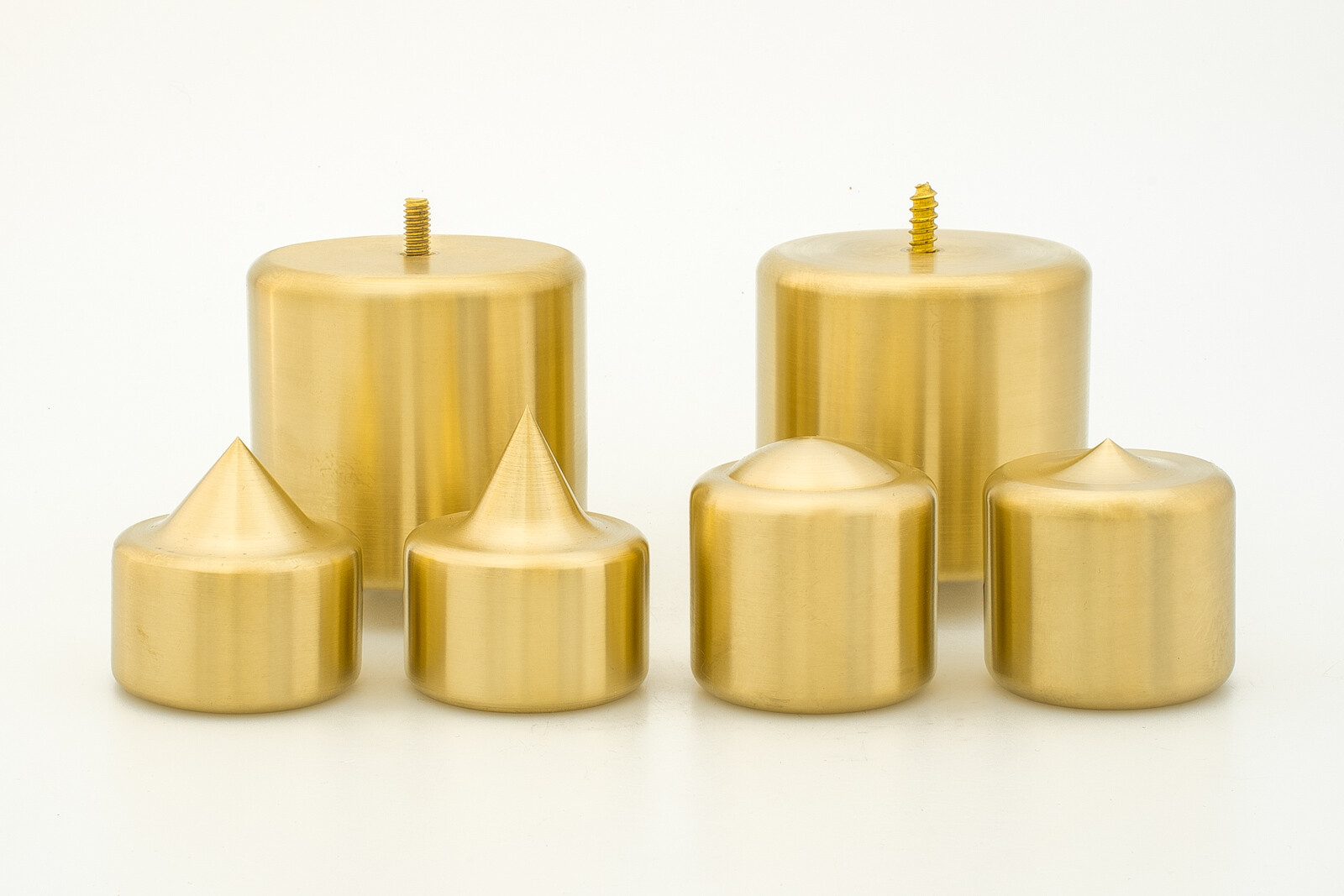
these are the parts we want to make. ive also learned we will take a hit on machine time due to not being able to feed 2" stock through the machine, but we dont have the space for a machine that could do that.