The Tormach documentation for their spindle speeder says:
The Tormach Speeder is rated for 20,000 RPM output, but can handle speeds of up to 30,000 RPM output for short periods of time. These kinds of speeds likely come at the cost of belt and bearing life and will definitely make more noise during operation. That said, we have not seen much detriment to surface finish at speeds above 20,000 RPM.
This is a little vague and kind of says “don’t run your speeder at 30K for long periods of time”. It’s understandable they are saying that doing so will probably shorten the life of high speed bearing.
I am not a production shop and would not be running the speeder all day at top speed, but I would like to feel OK about running a single setup/operation at 30K that might take up to an hour.
I’ve done a couple of runs at 30K for about 10 minutes without issue but it does get quite hot!
My question:
Is the suggestion to not run 30K for long periods primarily because of the heat build up in the bearing? If so, would it be worth it for me to make a water cooling jacket for the lower high speed (ceramic?) bearing?
Or is the bearing simply not rated to run at 30K for long periods?
I’d like to feel confident that I can use tiny end mills for somewhat extended runs (30 min or more but not hours). The total run time on the spindle is likely to be very low as I’m a basement hobbyist - I use my machine a few days a week and most of that is not going to be with the speeder.
Adding cooling would not be that hard, but not worth it if there is some other fundamental reason for the speed limit.
Don’t know much about the speeder but i would run a break in cycle of some sort. Forward and backwards. Temps should come down after??? run time. Personally I would be inclined to take it apart and clean the bearings of grease and put in good stuff. Proper amount too. At least take it apart enough to see if grease is dropping out or slung out. Don’t quote me but higher speeds means less grease fill.
Should have asked if it is oil filled?
At 30000rpm the forces on bearings is vast and varied. You can get things like cavitation in the grease if any moisture gets in it. Galling if the grease gets any contamination and even the bearing cage can just break. Heat is the main way these bearings fail by expansion and contraction of the grease. This causes the ingestion of moisture and contaminants which in turn cause the bearings to wear and fail. Basically spindle speeders fail. You have so many hours when you buy it and you get what you get. Uniform loading helps a lot so if you can program your tool paths in continuous cuts (I’m assuming light loads) you will get more hours. Also keeping the end mill as short as possible and depending on the speeder only profile cutting (depends on the bearings). That said what are you cutting at 30,000rpm? Also might be worth a Chinese spindle, I have a 28,000rpm water cooled that I run bolted to my tormach1100mx table. I blew up the original VFD and now it runs on a Siemens sinamics. It isn’t setup to mill but it could be bolted to the spindle and have a second offset setup pretty easily.
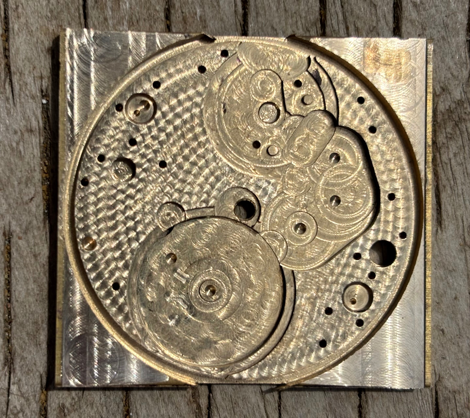
I intend to do it for cutting mechanical watch plates but it’s project 7 of 31 that I’m working on this week.
Very curious about what your making and how the finish looks.
@Bruce_Kuller @Dr_Harold_Jones - Thanks for the feedback.
I hadn’t put a whole lot of thought into how the lower spindle cartridge is constructed or what bearings it contains. I was just looking at it and thinking, it would be easy to make a water jacket that wrapped around the exposed part of the spindle.
I’ve been spending more time figuring out what I can do with my Tormach spindle speeder. I primarily do / want to do smaller scale machining for desk or table top sized mechanicals. It’s not uncommon to want to run a .01 or .015 end mill at more than 20K. Reading the Tormach documentation I was thinking that it might be useful to add cooling to the speeder.
After your comments and a little more research, it’s clear that just slapping a water cooling jacket on the speeder nose is not a great idea.
A better approach would be to stick some thermal sensors on it and see how, where it heats up and also what temp it stabilizes on at lower speeds, compare it to higher speeds etc. Then do some simple stuff to increase (even not blasts or high pressure) air flow and see if I can get it to run at a cooler stable temp at higher speeds.
At the end of the day all of this is a lot of work to maybe increase the life of the spindle cartridge. (which I have not had any problems with and I’m not likely to with my light duty cycle).
Even if I do eventually blow out the spindle cartridge, that would be a good time to consider other high speed options. For now, I’ll try to avoid operations that use high RPMs for more than 10 minutes or so.
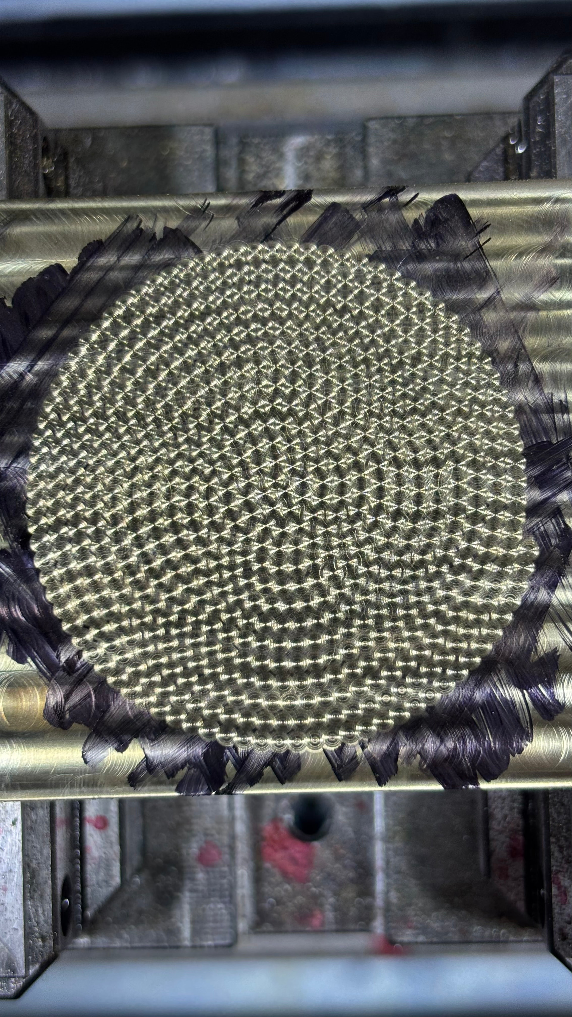
What got me to this point is I’m experimenting with what sort of results I can get using engraving / machining to mimic real gilloche - fine machine engraving.
If you have any examples if gilloche that you’ve done, I’d love to see it
Not quite guilloche but not bad for a day.
I haven’t tried any patterns with a fly cutter and a rotary table yet.
Very cool!
Is that pattern made with a EM of some kind?
or the rod and diamond paste method…
Just hard to tell what that pattern is in the first pic
But very sweet
I tried a lot of things but the most repeatable was with silicon polishing buffs. The pattern was just supposed to look like pearlage. It needs a little more refinement.
I also did a weeks worth of experimenting to get a brushed matte finish on aluminum with a brass wire cup. The secret for that ended up being that you have to spray it with alcohol on the second pass. Some kind of weird chemistry or very specific heat buildup.
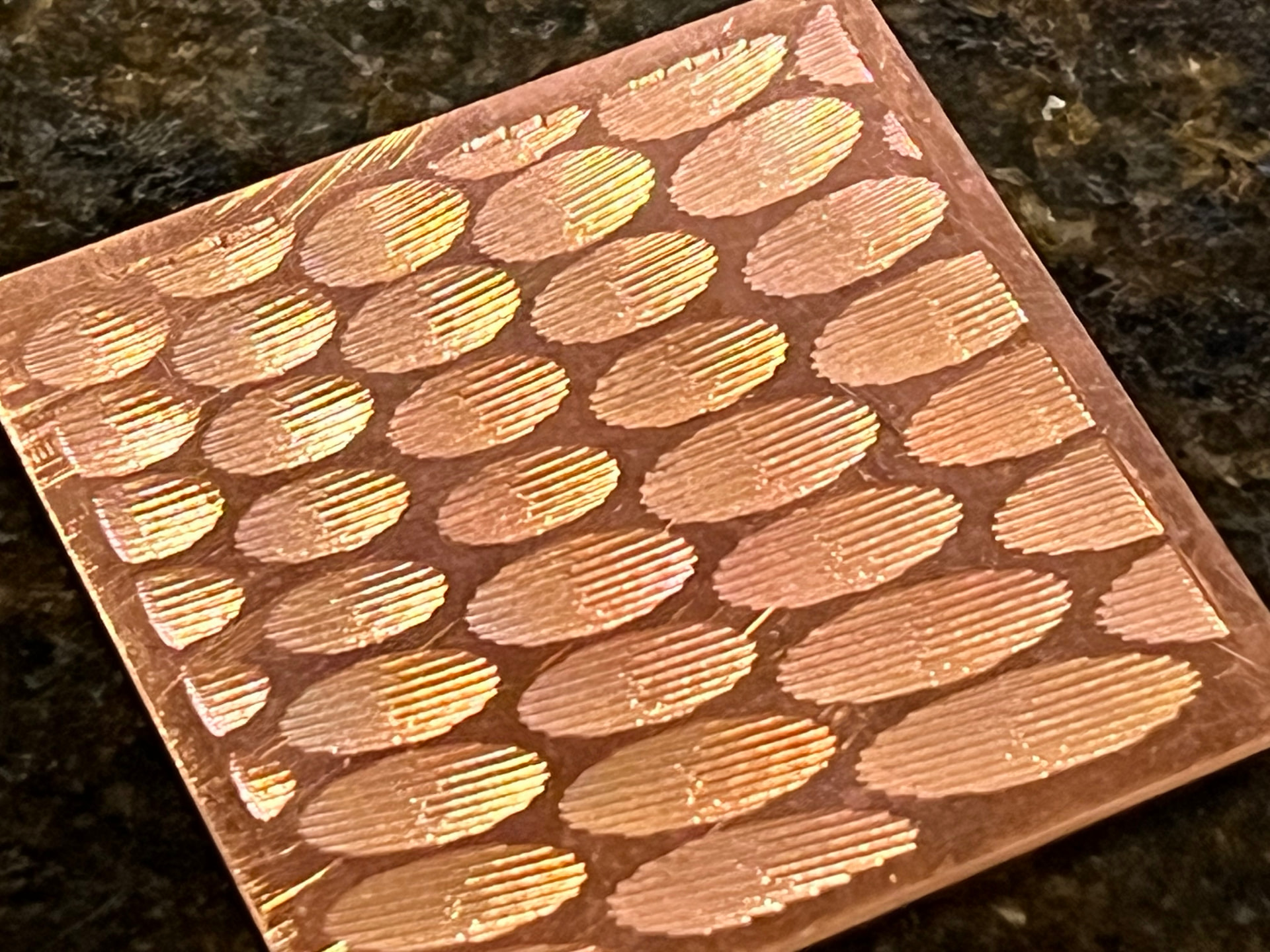
This is literally my very first attempt, as cut right off the mill.
I’m planing on transparent enamel so the tests are on copper. The square is about 1.5” sides. I generated a 3D model with varying size ovoid divots. The ovoids are about .008” deep. I then used the parallel 3D strategy with a .04 ball mill. If you look closely you can see that I varied the parallel direction to achieve a curved affect of the overall line work.
From my perspective, this came out remarkably good for a first attempt. The camera picks up everything. The scratches on the flats in between are very small and just catching the light.
The most obvious machining mark/defect is some noise in a vertical line in the centers of the divots. This is caused by the backlash compensation that kicks in a the appropriate middle of each cut where Z changes from down to up as it climbs back out.
I think that a fine steel or brass brush might soften or remove those marks.
I’m now in the middle of trying more tests and patterns.
It looks really good. I haven’t made it to the enamel yet but some of your problems might be solved with an ultrasonic cleaner and solvent and lapping. For all the jewel quality you always have to polish everything. Also I think the enamel can be quite forgiving as the glass sort of self smoothes everything. But it could be just the opposite and enamels simply refuses to stick to any surface that isn’t already perfectly smooth.
Enameling on (at least) copper, steel, silver & gold is somewhat surprisingly a chemical bond between the glass and the metals. In particular the metal surface develops oxide because of the heat before/as the glass is melting as the glass flows and fuses the oxides are absorbed into the glass at the metal glass interface.
To prepare the metal the single most important thing is a clean surface, for copper this usually means a pinkish mat surface out of a pickle bath or a scrubbed / mechanically clean surface.
Adhesion is not usually a problem, regardless of texture, it’s the coefficient of expansion difference between the base metal and the glass, there is a relatively narrow range that will work well for the first base coat. Nothing more annoying than pulling a piece out of the kiln and listening to it start crinkle and crack as little bits of glass fly off as it cools. Subsequent coats of glass on glass are more forgiving but still need to match COE to some extent.
With gilloche, transparent are used (what would be the point of covering the pattern with an opaque!) at that introduces the additional issue of firing to the point where the oxides defuse into the transparent glass. This actually is essential to develop the transparent’s color (some colors more than others). Oxide remaining on the metal will of course reduce the sparkle.
I haven’t examined the my first piece with an inspection scope yet but I’m willing to bet that the center Z change marks are just little ripples due to the backlash comp. A fine polishing compound used lightly with a soft-ish lap may be enough to reduce them without destroying the cusps created between the ball mill tracks.