I wanted to share a good option /method for setting z offsets on lathe tools that can’t be touched off face used by reference tool.
I also posted this on instgram and figured readers here might benefit from this method
I have struggled with this for a while. I used a head set magnifier to do this in the past and it was less than easy and depending on angle of view less than accurate.
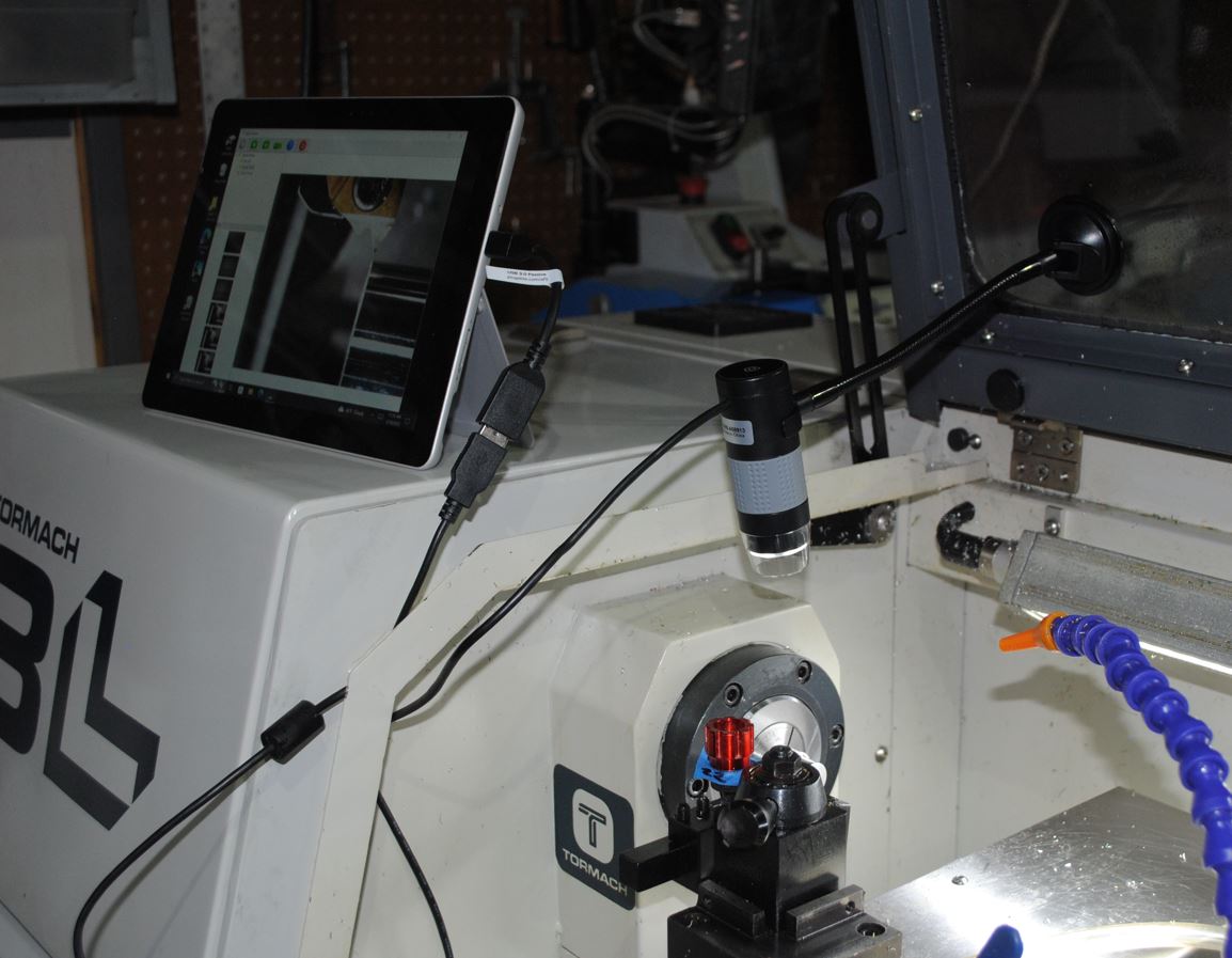
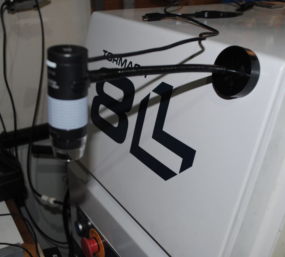
Using this USB microscope and a tablet to view picture makes setting z lathe tool offsets so much more manageable.
First picture shows the microscope and tablet viewer. I now can stand back and position tools as desired making it easy to set z tool offsets on lathe tools that cant be touched off the reference face set by the primary lathe tool.
This should increase the overall accuracy of the offsets for thread, part off and neutral handed lathe tools. And thus programs that use these tools will have more predictable results! Thats my theory anyway!
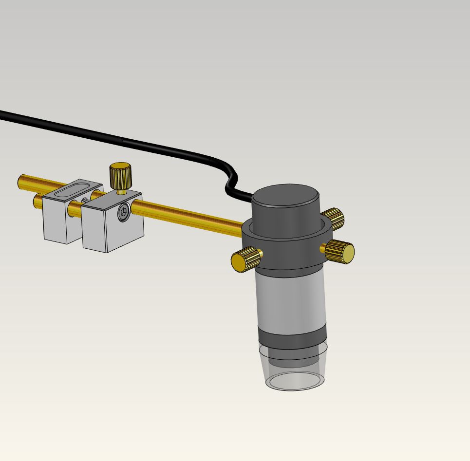
Simple mount in fab que to replace the suction cup mount that requires a clean surface to work. Rev 2. will use this for testing and overall ease of setup.
Thanks,
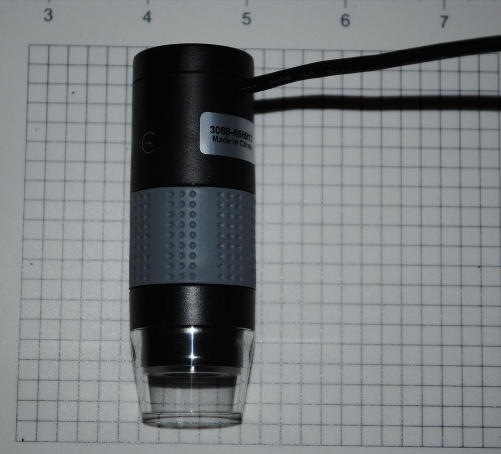
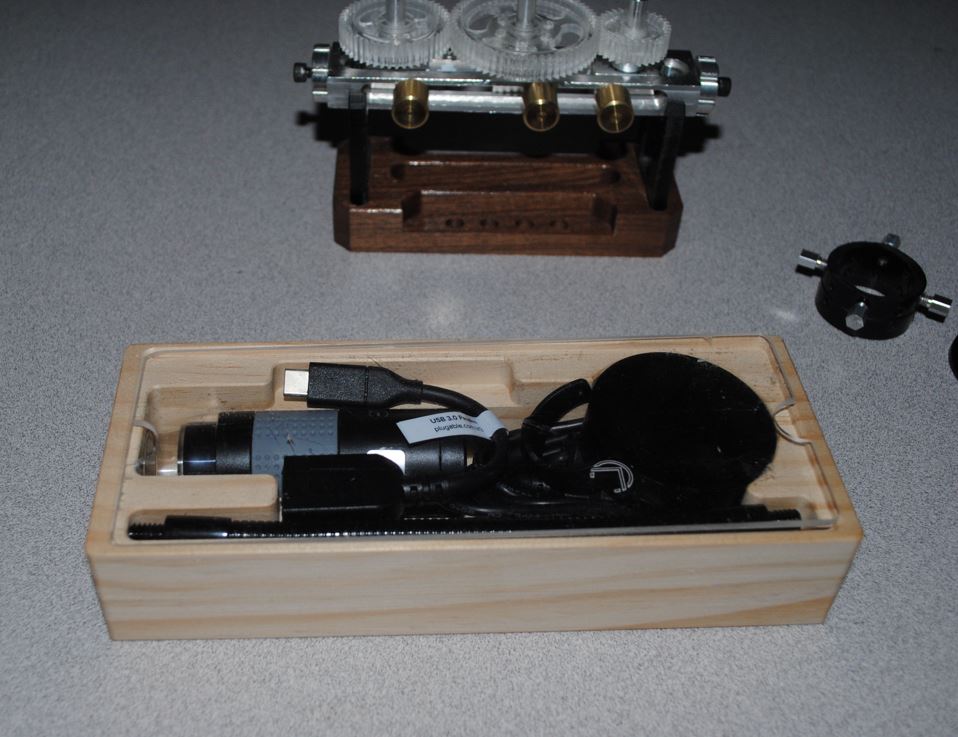
The unit shown is made by pluggable and cost around 25$ cheapest most useful tool I have purchased in years. I tried a few different ways to mount it and settled on a magnetic base. Clamping on sheet metal was to fiddly and took extra tools, suction cup didn’t work on dirty surfaces. Magnetic base works best and allows quick placement and removal when done. Will post picture of finished mount.
Pictured of the magnetic puck style mount for usb microscope
As mentioned above this one is much more easy to use. no tools and it can be moved around or moved out of the way easy! keep it simple!
Thanks!
As mentioned above I find it hard to accurately set lathe tools that can’t be touched off the reference face that is set by the primary tool.
I would like to know how others set z tool offset of left-hand tools or neutral tools like threading tools and both x and z tool offsets of Internal threading tools, internal grooving tools. If there is no face to touch off. How else can it be done?
Always trying to learn new methods from other users. Most people I asked said they set them visually or with a tool setter on high end cnc lathes with built in special tool setters.
Any comments, methods or ideas are welcome!
Great question. I always wonder the same thing. I can’t say that I’ve really nailed the left hand tool thing. What I do on neutral tools is I caliper the width of the tool holder (should be 0.75" in most cases) and touch the outside of the tool holder and subtract half the width. This is making a lot of assumptions about the accuracy of the position of the insert in the middle of the holder, etc. but I haven’t come up with a better idea. Would be great to hear what others do.
The other tool I have is a Fowler Edge finder. It’s not bad for touching off the front with odd tools. I have speculated that maybe if I mic’ed the length of the tip I could touch LH tools from the other side, but I haven’t tried that.
Thanks for the reply!
I will add one of these to my tool collective. Little better visual aid for this I think.
I messed with a .2 diameter wobble edge finder for checking and setting x diameter of threading tools and found it improved the threading accuracy a little. When i was just touching it off the surface diameter I was getting threads that could vary based on how I did the actual touch off. By using the edge finder turning at 500 rpm i could see when it aligned and then verified the diameter on the PP dro field! I even posted a short video on IG a couple years ago showing that method! And I still use this method for threading tools!
But I had never seen anyone do it this way.
Using cam for all my lathe code is nice but It requires a very exact description of tools in the tool library because it generates tool paths based on the exact shape of the turning insert. Using conversation code you can kind of run and check dimensions then change code on the spot and rerun until you get desired results. This method you can somewhat get away with a little less accurate tool table and tool offsets!
Anyway great Idea for another setting aid!
Yes. I agree with the accuracy needed on the CAM side. I also find most of my turning work is in the sub 0.002” accuracy range, so that’s an extra source of stress on set-ups.
I actually generally employ a hybrid approach…. I use the edge finder to get Z pretty dialled, and then to set an initial X. After that, if the job is really tight, I will usually run conversational passes on a scrap piece and go adjust the diameters based on what I actually measure. It’s sort of the only way to get things really really dialled in, I find.
I find a CNC lathe super easy to operate but fiddly, time consuming and even frustrating to setup. Sprutcam is easy to get code to turn from complex models but as I mentioned above its not as accurate because the insert on the cutters are a complex shape also and depending on approach and generated tool paths some features will look great but are not very exact. Simple example is a male compressed air quick connect coupler. Easy to make ones that work. Not so easy to make ones that dont leak air at 150 psi! As you mention you need to adjust or tweak code at machine to get best results.
Looks like a decent solution, thanks for posting
Looked at web site and it says request a quote. For a small tool for offsets, ok!
If they don’t publish a price and price it depending on who asks is a business model I don’t support much unless I have too.
I won’t bother with a quote from this company!
Just my preference.
Thanks for info anyway
OK - but they don’t really care and you miss out on a fantastic tool - I have one I use on my 15L all the time. If you look around a little elsewhere, you’ll find the price.
I understand and I figured it was a decent tool. If they had a price, I would have considered ordering one right then.
And I know they don’t care if I buy or not! Everyone has their own way of doing business!
I have no problem with the company just the lack of price and needing a quote is silly on a tool setter imho! Machine or system yes but a silly tool
Anyway, I like my 25$ solution for now and will keep their link for reference! Maybe even make my own copy of their tool to test and use. lol
Thanks again for the post and sorry for the aggravation I caused. Nothing personal.
Hey thanks for link and price! I figured it was a bit pricey. If you have to ask! lol
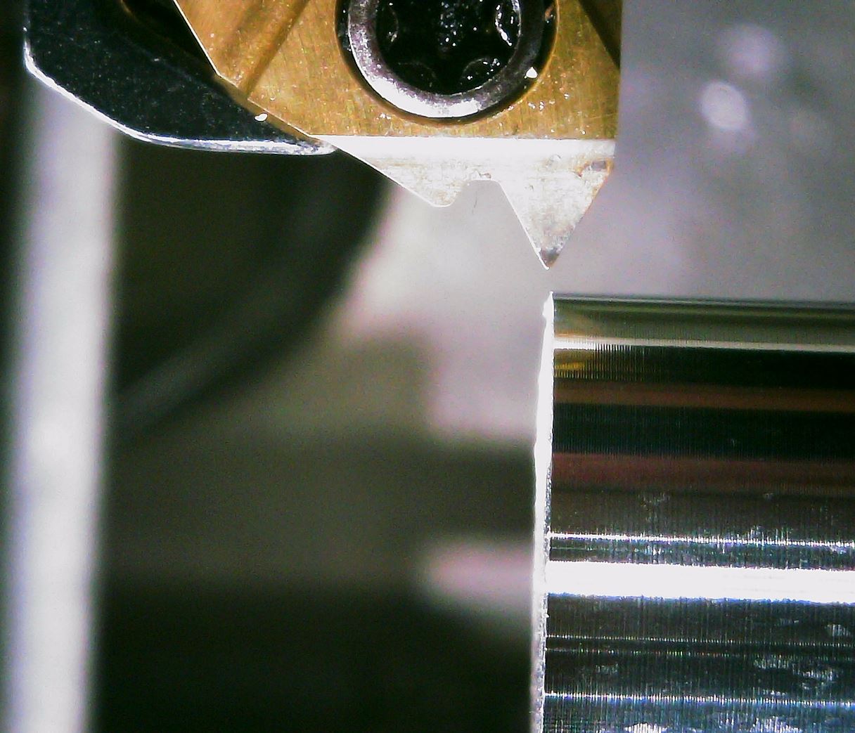
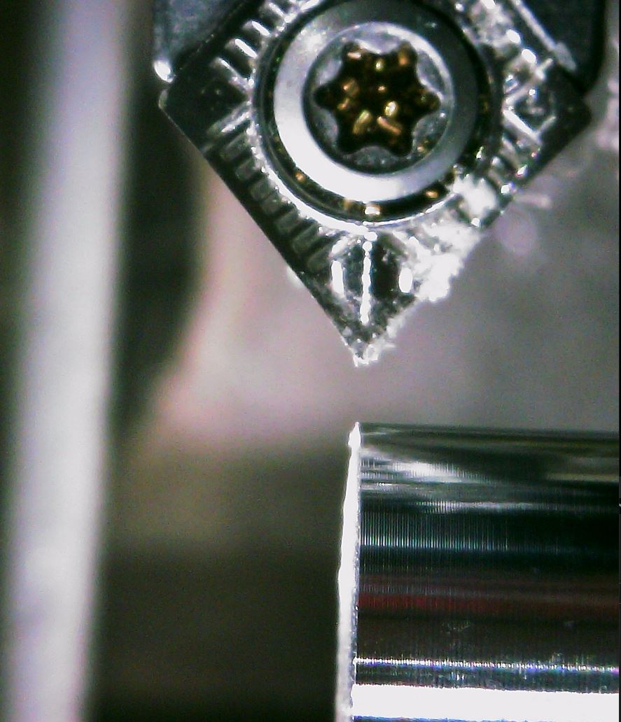
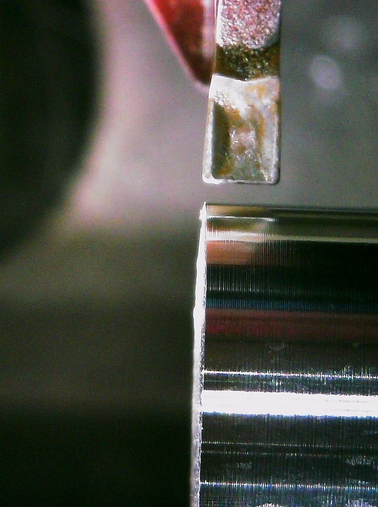
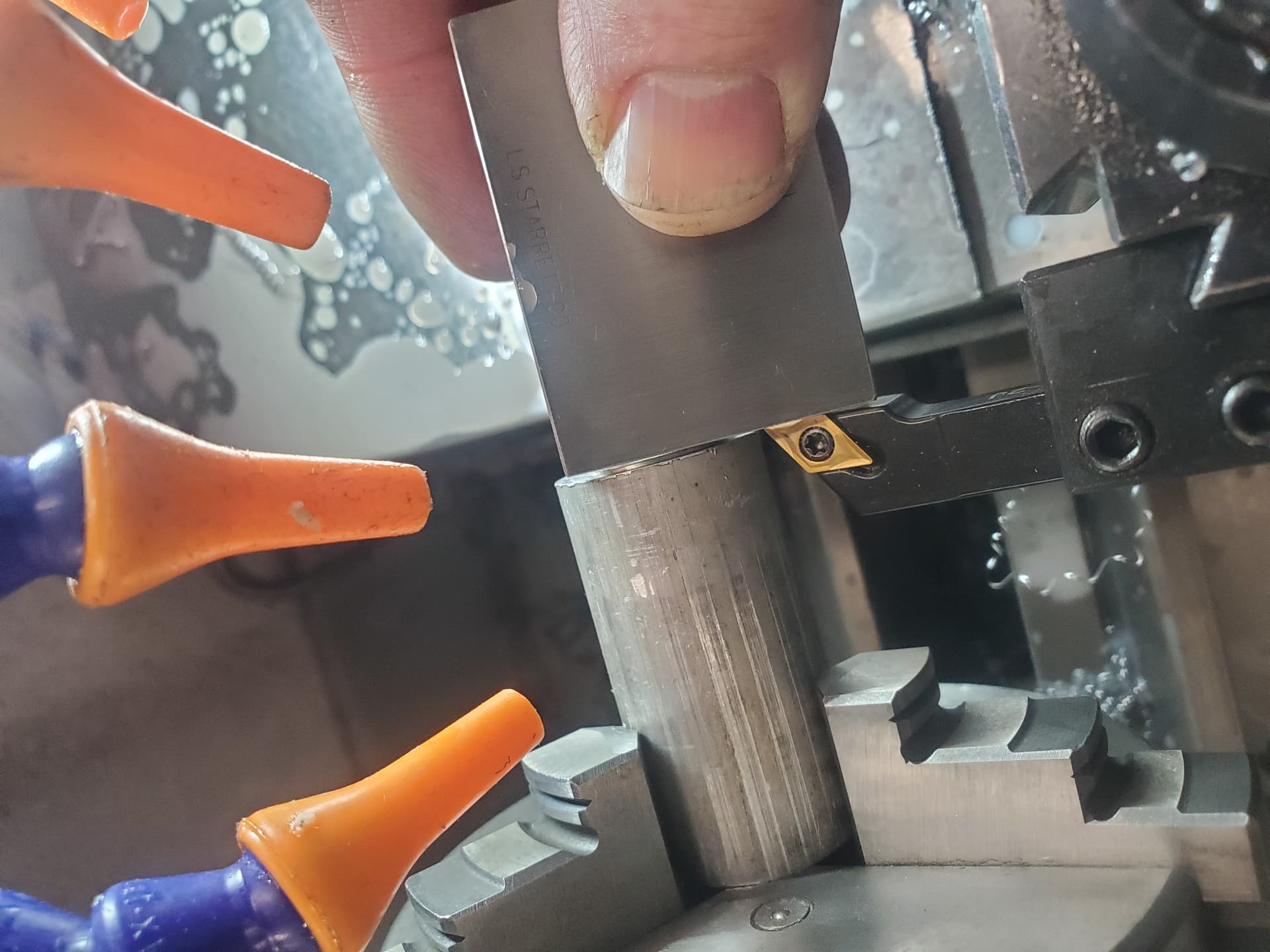
I was looking and still not clear how well it would work for z offsets of internal and external threading tools and no hand tools! Not clear to me how i can align the center of the lathe triangle shaped tool insert with the reference face to set Z offset. Looking at the pictures I show above it would be hard to touch the center of that point against any reference Z offset surface. A combination of both microscope and setter would be very useful system I think. Best of both.
Maybe im not seeing how this works completely by just looking at their diagram.
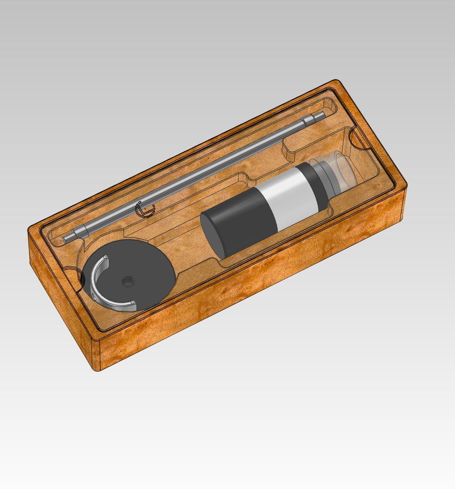
Oh and just for fun I had to make a storage case for the microscope and accessories!
What can I say I have a 24r router and good cad cam work flow! Makes these little projects fun!
Threading tool - don’t set the point, set the left side. 1st, it is way easier and 2nd and most important when you program length you don’t have to figure out clearance, you can turn a .370 diameter x .75 long and then cut the thread .745 long without worrying that the tool will hit the shoulder and get max thread length.
POT - set the left side. Conversation programing has a location for the width of the tool and you can type an equation in the z (or x) box - e.g, to part off something .75 inch long with a POT that is .080 wide type in the Z entry box “.750+.08” Same as you can type a fraction it will do the math and convert to decimals.
If you insist on using the RH side of the POT, touch off on the left side to a face and in the Tool Offset window type .08" for the offset.
I have about 15 tools set up in my 8L. They are all +/- /001 on the Z. To set the LH tools to a know face I use a gauge block or even a ruler held against the face and touch the tool to it. You can easily feel a light touch and get the z offset with in .001 inch.
I tried an LED edge finder and a few other tricks. In the end, the best way was the simplest. It is also important to note, that drills, threading tools etc. don’t have to be perfect, .005 is close enough.
Don’t try to overthink things, it takes away from making parts.
Thanks for reading and comments Tom
You outline pretty much the methods I used for the first couple years and still use depending on what I’m doing.
I dont use conversation programming at all. I use only cam with part models. My cam requires well defined tools in its tool table to generate accurate tool paths and gcode. Part off tools can be set left or right side and its more a habit and I have 4 different parting tools that have different inserts or tool widths. So I find right side less error prone. cam will also profile and chamfer and part of in same operation with same tool. I also have a dozen different left hand and NO hand profile tools. as you show a few can be set with a simple block against face but a few and the NO hand tools cant! For cam to generate good paths and for those paths to be followed I need the NO hand tools to be a close to center of insert as possible.
I have tried and use a number of different methods for setting accurate tool offsets, I just tried and liked this one. and added it as an optional method to use. As you mention there are many ways
Part of the fun was it cost me 25$ and is kind of handy tool at that price!
And I will admit I do tend to overthink everything. But that has never hurt me yet! I have about 30 tools setup in my tool table. not including taps and drills.
I use on average 6 or less in any program. I do have material specific sets and this allows me to run whatever material i want and not setup a bunch of tools because I changed inserts.
Any way i enjoy using my 8l lathe and combined with good cam and big tool table Its easy for me to draw and machine about any form I want. Throw in my 1100 mill with 4th axis with same cam and I can get real creative combining operations from both machines. Just a nice tool system.
I would like to mention the tool in your picture above is what I consider to be sticking out a mile away from the holder, maybe even 2 miles ! That is the one of the things I avoid!
To the amount the tool is sticking out, I figured someone would comment. I was going to do a deep profile and needed the clearance. Typically they are in as far in as I can get them.
I wish it had more horsepower for parting. I find if the tool is at all worn it jams and stalls. I have tried everything from .001"/rev and different pecks. Basically new tip often. A carbide PTO tip should run from .005 to .015/rev, usually .010 is a good starting point. (feeds according to Kenmetal and Sandvic) You need the feed rate to form a good chip that the insert makes narrow to clear the groove. Hard to do on an 8L.
I cut just a small recess with the grooving tool in the location where I want the part off to be. When the finish turn is done I pull the part and cutoff with my manual lathe. There is just no replacement for a gearbox when parting off.