This is probably something relatively simple but I need help. So I have created a program using 3 different tools. I have all the tool lengths entered into the Fusion360 library and also manually entered them into the controller library. I touch off T1 to the top surface of the part and set Z0. I run the program and T1 operates perfectly. T2 and T3 however do not go to the correct depths. Thankfully they are shorter tools and do not go deep enough. I have to touch off each tool to the top surface and set Z0 before running the next operation.
How do I set Z0 once so the controller knows where the part is in space, and then make tool changes without having to set Z0 each time?
The tool lengths in fusion won’t change anything PathPilot wise.
If you are going the route of using a master tool, you can set you G54 Z to 0 as well as your tool length to zero. Then, your T2 and T3 when touched off and changing the tool offset only, not G54, will only show the difference between said tool, and T1.
If you want to use the exact values in the library you already measured, touch off the top of the part with your spindle nose, with T0 active. (I am assuming your tool lengths were the measurement from the shoulder of your TTS holder, to the tip of the tool.)
We teach a method called ‘true positive tool lengths’ in that video, which has the advantage of being able to measure tools either in the machine or with a surface plate/height gauge. The method Sam describes will work if you measure all your tools in the machine, but you won’t be able to mix and match with tools measured on a surface plate.
All the controller cares about (PathPilot or any other CNC control) is that your tool lengths are correct relative to each other. In Sam’s method, the ‘master tool’ is tool 1 with zero length, then the other tools lengths are just their relative differences to tool one. In the video I link, there’s no ‘master tool’ and you use the spindle nose to set the G5x Z0. Subsequently all tool measurements are equal to the distance the tool sticks out from the spindle. I like this method because it’s conceptually easier, and as mentioned before, works with the height gauge too.
Thanks for the responses! I was making a mistake and entering the stickout length into the controller for the tool offset length. Not the true tool length. And then I was just resetting my G54 Z0 for every tool change.
Now I have the true tool lengths measured with the height gauge and entered them into the tool offsets. And with T0 active, touched off the spindle nose to the top of the part and set Z0. So now I should be able to run the program and make tool changes without resetting Z0. Thanks!
I have another question regarding programming using Fusion360 and hoping you can help me. I have two different setups and want to mill a hole into both ends of a part using the same endmill. They are different diameters. I just want to reorient the part end for end between setups.
I ran the program and it completed both operations consecutively. There is no stop to allow me to change the part orientation. How do I add a stop into the code? Can I do that in Fusion or does it have to be entered manually into the .nc file? Can I just add an M6 line to call for a tool change?
@Kyle_D I’m on mobile and don’t have fusion in front of me but you have a few options here. I
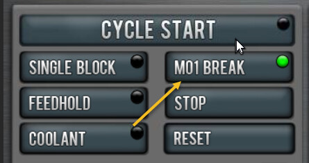
in the options that you are given when posting your project there is a check box that offers the ability to add an m01 break between operations which will put a break between every tool path
if you have several tool paths in each operation then you can add a manual NC line.