How to get a 3rd party wired ETS working on the 1500mx?

Hello all,

I’m trying to set up a 3rd-party tool setter on my 1500mx.

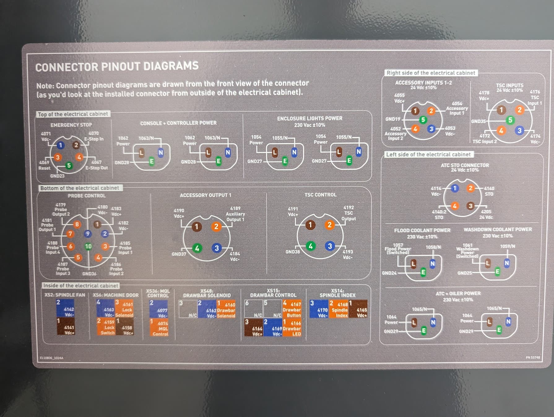
The 1500mx manual says to wire an ETS into the Accessory 2 port. But I think that may be left over from other Tormach models. I don’t have a separate accessory 2 port on my 1500MX, only one accessory input port with 2 input wires in it, and those don’t seem to do anything with the ETS.

I read through the install for the 1500mx wireless probe and tool setter package, (which I don’t have as it was expensive, and I don’t need a probe, just a tool setter). The receiver for that plugs into the “probe control” port. After some experimenting, I wired my ETS to “probe input 3” in that port, and set it to pull the input down to 0vdc when the tool setter is pressed. This makes the “ETS input” indicator on the “ETS setup” screen turn from off, to red, whenever the ETS is touched. So I thought I was close there.

However, if I try to use the “ETS spindle Reference” button, I get an error “Probe not ready within 10.00 seconds”. I’m guessing it needs to see that the wireless receiver is active on the other inputs. I’m open to jumping those inputs if possible, but the timeout makes it seem like there may be some active communication happening there.

I’m completely new to both Path Pilot and using an ETS, so I might be missing something simple here. Any suggestions for getting a basic, wired, one-input tool setter working on the 1500MX?

Thanks for reading!

Not sure if the 1500 uses the old short detection system as the last generation of mills. If it does there’s hope.
What I would do is put a wire to that connector and see if you can get the ets probe trigger light on path pilot to turn on or off. I f there are only 2!wires in the port it’s probably 12V and 5V using the plug housing to ground. Check the 1500wiring diagram. If you find that and the tool setter wiring diagram send a picture and I will see if I can help.

If it’s using the usb bus I have no idea.

I had a hell of a battle with my tool setter on my 1100mx. My tool setter has 5 wires but the port on the 1100has 4.

Wireless probes/ets’s (ets’? don’t hate me grammar police) will go to an idle state after a period of inactivity to save battery life. When they need to be used a signal is sent over whatever communications protocol is used to wake up the device which then responds with an “I’m ready” response. I haven’t fully disected the owners manual but I suspect the communications protocol is not documented there anyway and there is precious little in the way of photos of the probe, ets, or interface module. BUT!! In the owners manual, there are a few terrible photos of the different components and between them, you can just make out the brand name Pioneer, and the text “400” on the probe, indicating an OPS-40 probe and it’s associated module. Documentation, including the wiring pinouts can be found in their owner’s manual here

@Dr_Harold_Jones The 5th wire on your tool setter is likely an overtravel alarm output and can be ignored since your 1100 isn’t setup to detect or respond to that.

1 Like

Yea but is there a way to say “I have a wired tool setter” and skip the if no response then fail?

Definitely put in a ticket. Tormach support likely has a script to insert to override wireless system wake status. Maybe….

Thanks for your responses.

As far as I can tell, all the IO in this machine is 24vdc and comes from the servo drives. The servo drives connect to the PC through Ethernet cables (EtherCAT protocol) Each servo has 5 inputs and 3 outputs built in. See port CN1 on this diagram from the servodrive docs:

servo pin out.pdf (323.0 KB)

Tormach has a ribbon cable running from each of the drives to a Tormach-made IO board that reroutes them as necessary. So all the I/O is communicated to the PC via the EtherCAT protocol (I think). Unless you add the USB I/O module, but I don’t have that, and I would worry about speed/lag if I were using a tool setter through it. I’d rather buy a separate ethercat I/O module if I needed to.

relevant pages from the electrical prints:

1500MX IO board diagram.pdf (66.2 KB)
1500MX IO diagram.pdf (62.3 KB)

And here is the very helpful ports pinout they put in the electrical cabinet:

This morning I double-checked and tested all the inputs on connectors J3, J4, J5, and J6 on the IO board. The only one that had any effect on the “ETS input” indicator was wire 4187 on J6, “probe input 3” .

Ian, great find on the OPS-40 docs. That clarifies a lot. I get a “probe/ETS reported low battery” message when I try the “ETS SPINDLE REF” and the diagram you posted shows an input for that, so it makes sense.

So, assuming there is no easy way to get this running, I see two options: I could probably hook up a PLC to the probe inputs and play around until I fool the control into thinking it’s a wireless receiver. That’s option one and I have experience doing that kind of thing on other CNCs.

But, I would prefer option two, which is where I modify the control somehow to just use one input. I have no experience with linuxCNC or pathpilot, but I would like to learn so I can do further automation stuff with this machine. I am an OK coder, python, ladder logic, etc., and I can learn whatever language I need to. But I’m completely lost when it comes to the architecture of how all the IO gets passed around and where the code that runs this ETS subroutine actually exists. I’m thinking I could either modify that subroutine or I could review the code to understand how it works and write my own separate subroutine that utilizes the accessory input to achieve the same result.

Here is a link to some more docs, including the full electrical print and servo drive doc, plus photos of the IO board: 1500mx electrical/IO - Google Drive

I’ll keep poking around, but any suggestions or links to relevant info would be much appreciated!

Thanks

Other people have successfully modified path pilot to serve their unique needs, there is a group on Facebook dedicated to such things, though it doesn’t seem to be heavily utilized. The thing to bear in mind with any PP mod is that most will have to be redone every time Tormach releases an update. From what I can tell, each new update of PP adds a folder to the file structure on the controller HDD. I assume there is an initial boot sequence that polls those folders and selects the highest number to use as the current version to finish loading. So if you make changes to 2.12.2, when 2.12.3 is released, you will need to make the same changes again. Not the end of the world but a bit of a pain to remember.
Without doing another deep dive into things to work out the communications protocol, I suspect your solution could be a fairly simple arduino project rather than going full PLC, maybe even simple relays. Presumably, the controller sends power to the probe through Vdc+, then sends a wakeup command through one of the probe’s io channels before waiting for a response via another (or multiple other) io channels. If the relays or arduino are wired/programmed to activate when the wakeup command is sent and provide the appropriate response through the appropriate io channel, the controller will think everything is as it should be.
If the responses are nothing more than high/low signals, relays should work just fine. If it’s some kind of serial interface, then the arduino would be necessary. Either way, doing it this way saves you from having to dig into PP, and the changes will persist through software updates. You’ll also likely have a sellable product for others looking to do the same thing.

Ethercat is very well established there is likely a very cheap board that could be plugged straight in to respond to this signal and allow the normal probe macro to execute. Also I don’t know anything about programming on Ethercat interface.