I bought a new Renishaw OMP40-2 (probe) and an OMI-2 (the receiver / interface) off Ebay. Trying to figure out how to make it work with the PCNC 1100 s3. Renishaw’s manual is beyond my understanding. Just wondering if any of you guys have made any attempts at something similar. The OMP40-2 is wireless, which is the big driver here. I”m close but no cigar yet; I have the probe working and the receiver wakes up, but so far, can’t get PP to see it. One issue is Tormach’s PP is looking for a Passive probe, NC circuit; and the OMI-2 can be switched to NC instead of NO.
I’m on a 440 (TTS) and not BT30, which was why in the end, I opted against the replica OMP40-2 (at least $300-400 more) and went with a GP800 (simple shaft mount into a ER collet for now and can mill a TTS holder with the right diameter bore later).
I looked at the OMP40-2 manual before buying. I think you have an easier job. You have two solid state switching outputs that are either NC and NO.
The older Tormach controls want a NC when you select “passive” probe. You need to wire to the two pins on the DIN with the NC terminals on the OMI-2.
Edit: I should have read your post more carefully. You’ve already solved the wake up situation (nicely done, a write up on that would probably help others)
Does your machine have the option to select an active probe? That should fix your NC/NO issue.
Renishaw have several receivers. The spec file I had downloaded is not the -2, it was another variant (-2H) which isn’t the same as this one.
First thing we need to know, is if we are looking at the same wiring diagram and not another variant.
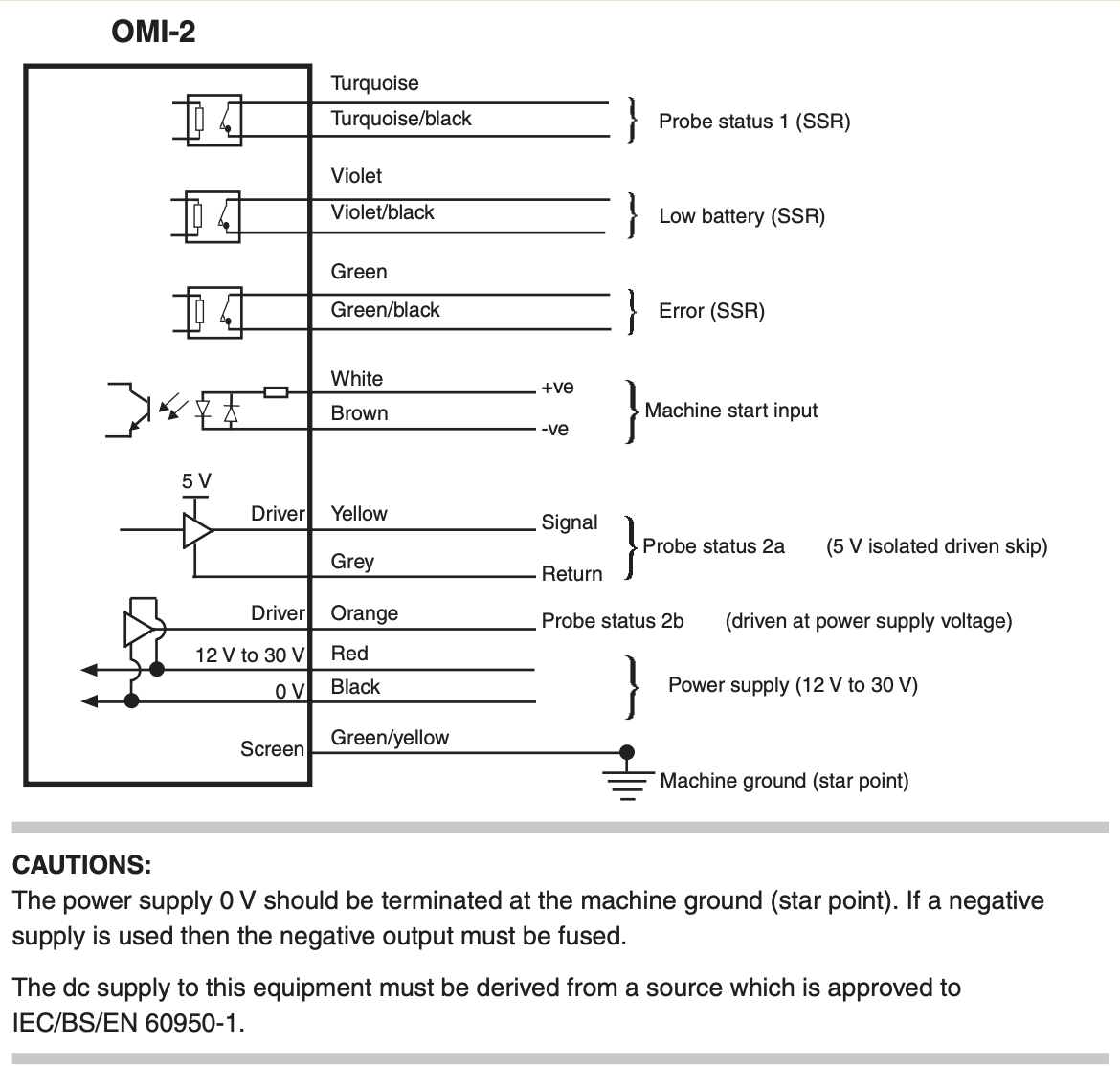
OMI-2
GND / +12-30VDC Power
GND/Power (-ve/+ve) for the internal relay contact for “start input”
Group A contacts are similar to what I have for the GP-800 for status but yours can run a different -ve/+ve than the main power
Group B contacts are also similar but yours can run a different -ve/+ve than the main power
The -2 (I was looking at 2H) provides a single pin voltage signal and does not close a contact.
You probably need a relay to take the signal from the OMI-2 and use it to trigger the relay which will close the two input pins on the 1100 S3 if you are wiring to the same two pins as the passive probe. On some of the older Tormach interfaces, those two are the only pins that are wired and there is no voltage at the other DIN connector pins. If you have a probe or ETS that is working, then you want to mimic what it does. Active on my machine switches the logic in PP from looking for NC to looking NO on the two pins.
I used a DIN rail solid state relay to eliminate the mechanical part of a relay contact closure and to not have to cobble together a prototype board with individual solid state components and it was only $12.
Ashraf_Farrag: Thanks for the response. I tried again tonight and I’m close but not working completely yet.
It’s my understanding that you need to provide power to the OMI on the Red & Black Wires. Also, Terminal 1 Signal is activated thru Turquoise & Turquoise/black wires. This should be a NC circuit that is controlled by Pins 5 & 4 on the Din Plug. I thus wired the acessory DIN plug as follows to the OMI-2….
Pin 1… 5 V measured output on Tormach– NOT USED
Pin 2 NOT USED
Pin3 12.5V measure output on the Tormach to RED wire on the OMI
Pin 4 Common / Ground – Wired to BLACK on OMI + Turquoise/black (Probe status 1 (SSR)
Pin 5 Turquoise – Probe Status 1 (SSR)
When I plug the DIN PLUG in with a battery in the probe, the probe lights up and after a couple of seconds, the OMI sees the probe and shows two green lights on it’s display. When I trip the probe, one of green lights on the OMI goes red as would be expected.
However, PP is not recognizing the proble being present. I can change SWITCH one to NO or NC on the OMI, no difference in PP. I have Pasive probe checked in PP, but PP never shows a green light on the Probe monitor indicator regardless. I can switch from Passive on to off on PP and nothing seems to cause PP to see the difference.
Can you clarify how you used a separate solid state relay to “activate” it? I”m assuming you used the SSR to close or open the Pin5 to Pin4 circuit?
I don’t want you to fry your Tormach board but the specs for the passive probe and any machine it will plug in to is that it closes two pins more or less like a switch and thus a normal relay if you have one for the appropriate voltage you are running can be used to test but I suggest using the SSR for the fastest response time to make it like a totally digital circuit without having to prototype one.
I think in mine, I am using the output from the probe to the “coil” + wire on the SSR with it going high on probe contact.
Ground goes to the negative SSR. The SSR “contact closure” on the SSR goes to the twoTormach DIN pins and then I have it set it to active probe.
Grab a multimeter and confirm your probe’s behavior…
I think I need to confirm what change is taking place in the OMI when the Renishaw probe is tripped aside from just seeing the green LED on the OMI turn red. According to the OMI-2 manual, it would appear that probe status 1 closes or opens the circuit SSR circuit for the turquoise and turquoise/black wires. However, I don’t see any difference when I measure the voltage on those 2 wires with a VOM. I tried looking at it with a small O-scope I have, but couldn’t make any sense of it. Once I can measure that, I can hopefully use that signal to close a separate SSR that will close the circuir between pins 4 & 5 on the Din circuit. Since all I’m doing is closing the circuit, which is what happens when I plug in a passive probe, I won’t have to worry about frying anything. Accordign to Tormach’s own data, the passive probe ONLY uses Pins 4 & 5 on the DIN plug; PINS 1,3,&6 apparently are used an ETS. I’ll try getting some more measurements tomorrow night.
Instead of volts try the continuity setting on your voltmeter. Those outputs could well be isolated from the Renishaw power source. If they are you might not even need the SSR assuming they can handle the Tormach signal voltage.
Watch out for electrical noise as well. I had a ton of really random things like spindle orient errors on my MX when I tried a poorly shielded active toolsetter.
I recall that others have found solutions for this with basic semiconductors. I had relays on hand that got me proof of concept and I switched over to the $12 SSR that mounts in an open DIN rail slot as a cleaner install. It’s possible there is some other solution that will work.
I have not researched the schematics of the electronic controls of this particular model/variant but the input logic on what I have, and it should follow that any Tormach mill that is listed as compatible with the passive probe, if you close the two designated pins on the DIN plug of the passive probe, you are following Tormach’s intended implementation and it should be guaranteed to work, as the passive probe is effectively a simple NC switch that opens on contact.
My GP-800 is all one circuit and operates at 24V where the circuits are isolated on the OMI-2. Maybe sourcing power for the OMI-2 elsewhere and using only the output pins of the DIN in some fashion will work.
Replicating a switch/contact closure should be a guaranteed way to get the probe to work if this model mill is listed as compatible with the passive probe.
My main problem right now is I need to have the OMI-2 give me change in state, when the probe is touched. The OMI indicates the probe was tripped, but I can’t nail down what elso changed. The manual indicates that Probe 1 status (turquoise & turquoise/ black wires) should change, but I can’t confirm that. So right now, I have a probe that indicates it changed and OMI led turns red from green, but I can’t get that change of state into the Tormach DIN plug. I can’t find verify that change of state on any wire set coming from the OMI. Even when I change the NC / NO switches on the OMI, nothing seems to change or make sense. EXTREMLY frustrating.
I have my wired probe, so I’ll just use it until I get alot smarter.
The OMI, OMI-2 and OMI-2H are all different and we should have started with you posting your installation manual and wiring diagram on here instead of me trying to find them at the end of a long day…
Can you now confirm that this image matches the installation manual supplied with your device?
If it does, then when the OMI-2 has gnd and power on red and black, when the probe contacts an object or is touched, if you put a voltmeter in continuity mode to the turquoise and turquoise/black wires, it will either beep or stop beeping depending on if it is configured as NO or NC or if in Ohms mode, it will go from open to 0 ohms (or vice-versa). You will not find voltage on those wires. They are there to open or close the voltage/current from the machine control inputs. It is an SSR output (the other two models have different wiring, so my earlier comments may have been confusing you) so lucky for you, you should not need an external SSR…
Red and black need to be GND and 12-30V from somewhere else. A separate wall power supply if you are not confident to find one in the machine would work.
Do not connect the GND or 12V (black and red) in the Tormach DIN plug.
Do not use pins 1-3 on the DIN plug for anything.
Machine start input also needs power
The last thing is if you have modified the DIP switches to put them back the way you found them and verify they are correct…
Last night, I double checked the wiring to the DIN plug one last time and found Something that was causing an unstable connection on the turquoise to pin 5 solder joint. I resoldered and everything seems to be working now! FINALLY.
PP sees the probe correctly now and it seems to functioning as intended as a wireless passive probe. So now we know….
I much appreciate everyone’s help. If anyone attempts to use an OMP40-2 with the OMI-2 receiver on the Tormach as a passive probe, you’re welcome to pm me for the settings.
Awesome that you are up and running and didn’t give up!
Can you clarify what your final wiring connections ended up being (and dip switches) so I understand what did finally work and did not work with respect to what you were able to use out of the DIN plug in case we end up needing to help someone else with a different version or other brand of probe?
I am not quite done with my GP-800 integration, as I want to get my ETS working in parallel so as to not have another wrong thing plugged in crash and will post that up when it’s fully fleshed out…