Flipping a part in SprutCam 15

Hi,

I have been trying unsuccessfully to do a simple part with a part flip in the middle. I am using SprutCam XV 15 Build 0.19 Rev ga.4x64GA

I have it set up to machine the bottom of the part first as the G54 then using the same position in the vice against the stop in X and Y. Setting the G55 in the same X0 Y0 as previously and the Z0 at the top of the part, leaving .010 thousands of an inch to clean up the top surface. I even rotated the part in the G55 setup 180 degrees. But every time It has the G55 coordinates on the upper left corner of the part where it belongs but the G54 coordinate is relabeled G55 and it machines the part from the G54 coordinate. I’m assuming this is something simple that I’m missing and is easily fixed.

I would have added the program but it wouldn’t allow me to load a .stc file. so now how do I do that?

Art

You might check the code that is generated for your program. Sprutcam might be showing the machine UCS and not the LCS but when you compile the code it does have the correct g-XX offset in the code for each side of the part?

Setting up parts on different ucs - G54-g59 on different sides or different vise locations can be done a number of different ways.
Have you checked for videos from sprutcam?

Lane,

Thanks for your reply! Side 1 is set as Global CS and side 2 is set as Local CS 1.

Art

I set up a local cs1-cs? for each side or location of a part.

Then use-reference them in groups of operations.

clip of the group of operations that use cs1 that is defined as g54

Cilp of next operation group that uses cs6 that is defined as g59 in this program

As you can see I setup a number of offsets and group operations to use that offset. The offset can be any of six sides of a part or six different vise locations or six different sides on six different vise locations. I do this all in one huge program.

Also note that sc15 does shows g54 label in the window even when its not. some sort of display error that I ignore.

Anyway when finished you can check code to verify that is is setting the correct g-offset before each group of operations,

side note, shown below with groups you just use from previous in the workpiece setup and workpiece cs

If you dont use groups you need to set the cs? for each operation

Lane,

Thanks, I’ll give that a try this evening.

Art

I’ve spent a lot of time trying to get the part to work properly when flipped. Mostly unsuccessfully. Then suddenly it clicked and worked. Still can’t set side 1 as Local CS 1. But it does work as Local CS 21, if I try it automatically changes it to 11 then 12 then 13 ect. Maybe playing with the coordinates in the edit active coordinates also helped. So it’s sort of working, the part has the G54 and G55 coordinates in the right location but, whatever I set LCS and the origin coordinates at it is duplicated in the opposite side. For example LCS21 as well as the X .02 Y .02 Z .015 if I change it on side 2 both become LCS22 with origin dimensions X 0 Y0Z.01. Any thoughts on this. I’m assuming it’s some setting I have set wrong.

Art

Let me try again since I think a screen shot will help explain the problem. So as the program is running at this time if I click on the direction arrows choose edit active CS, this is what I see.

Now the problem is if I click on the part 1 G55 side and do the same thing This is what I get.

It is duplicating everything from G54 side to the G55 side, all the origin coordinates duplicated from whatever one I edit last is duplicated to the other. If I correct the side 2 G55 info and And edit the box with LocalCS1 to Local CS2, both sides become Local CS21 G55 in the edit box and the Local CS drop down box next to the direction arrows. At this point in time the only saving grace is that I can close the part and purposely not save it and I get the original file with the coordinates for side 1 G55 correct and the G54 and G55 location is right on the part. Any thoughts?

Should have said the G54 X0 Y0 Z0 coordinates same for the G55.

This shows how to create two local coordinates. with one named lcs1 to g54 “top center” and one named lcs2 g55 set at “bottom center flipped”

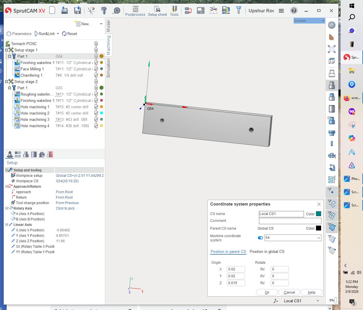
I started with a empty sc15 program on screen

lower right corner on tool bar are the two buttons needed to do this.

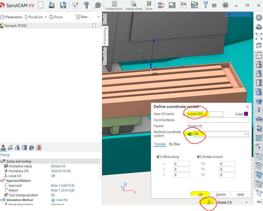
select button on left click and choose “create new CS dialog”

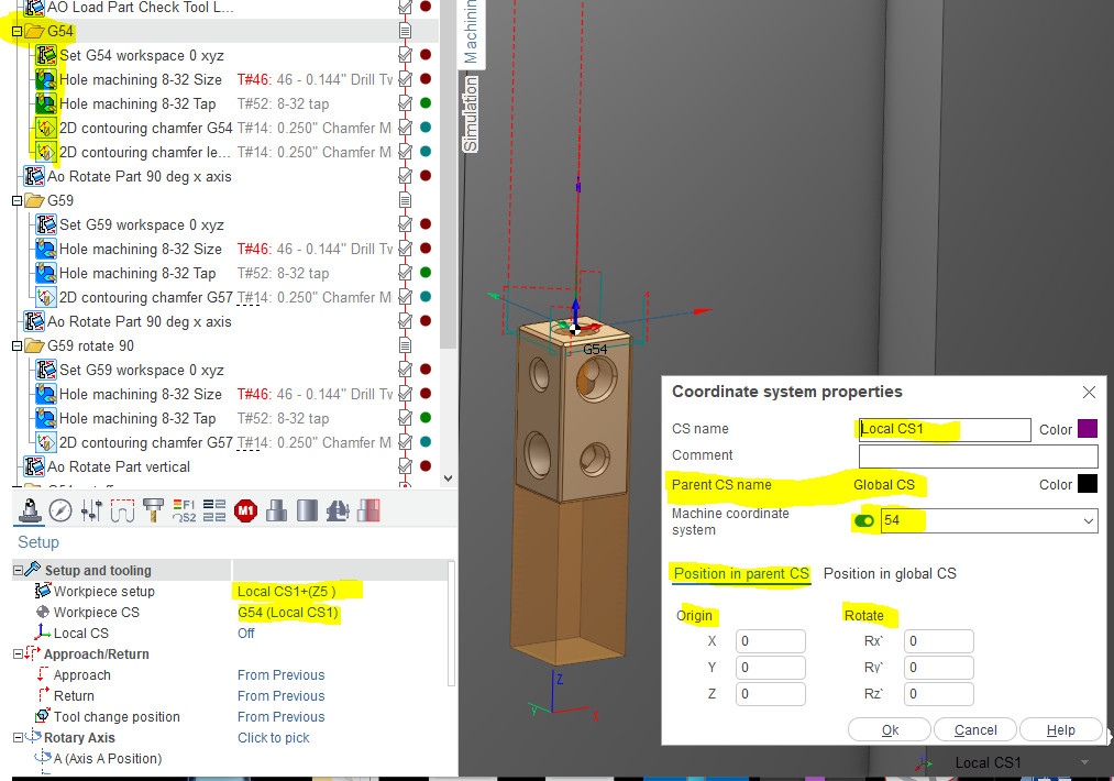
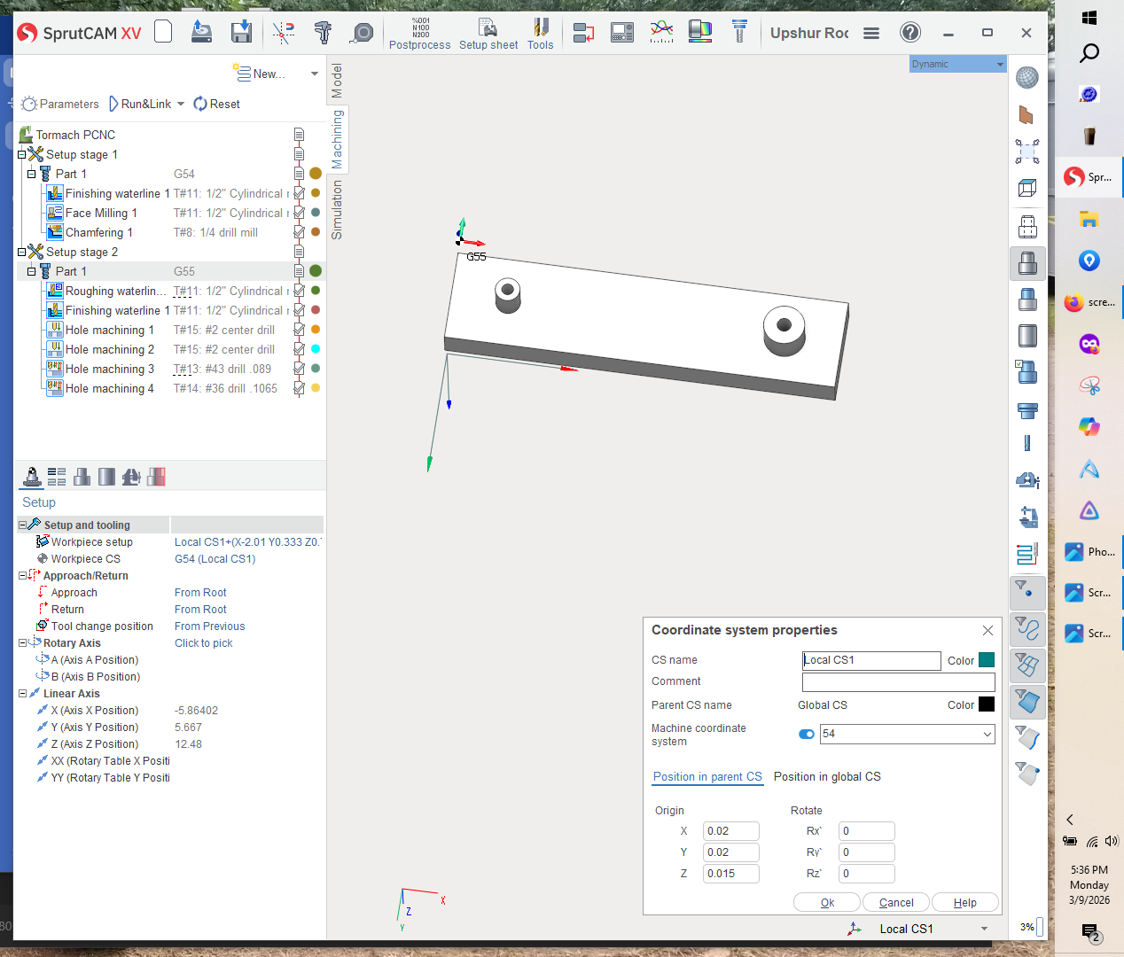
The follow dialog appears. sprutcam will auto name it in this case “local CS1”

and under machine coordinate system it put a 54 and you need to click slide button to enable as shown below. Not the location of CS1 -g54 is detailed in the offset along and rotate around x,y,z fields “all 0”

With everything set as shown click OK

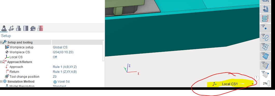
You now have a coordinate system that is set to top center of a part named “cs1” and it is set to machine g54 and the screen will show this in bottom left5 toolbar

Now change the lower right from local cs1 back to Global cs before your create cs2 This is important you need to create the coordinate systems under the global cs shown below

And create another local cs using the button on left click and choose “create new CS dialog”

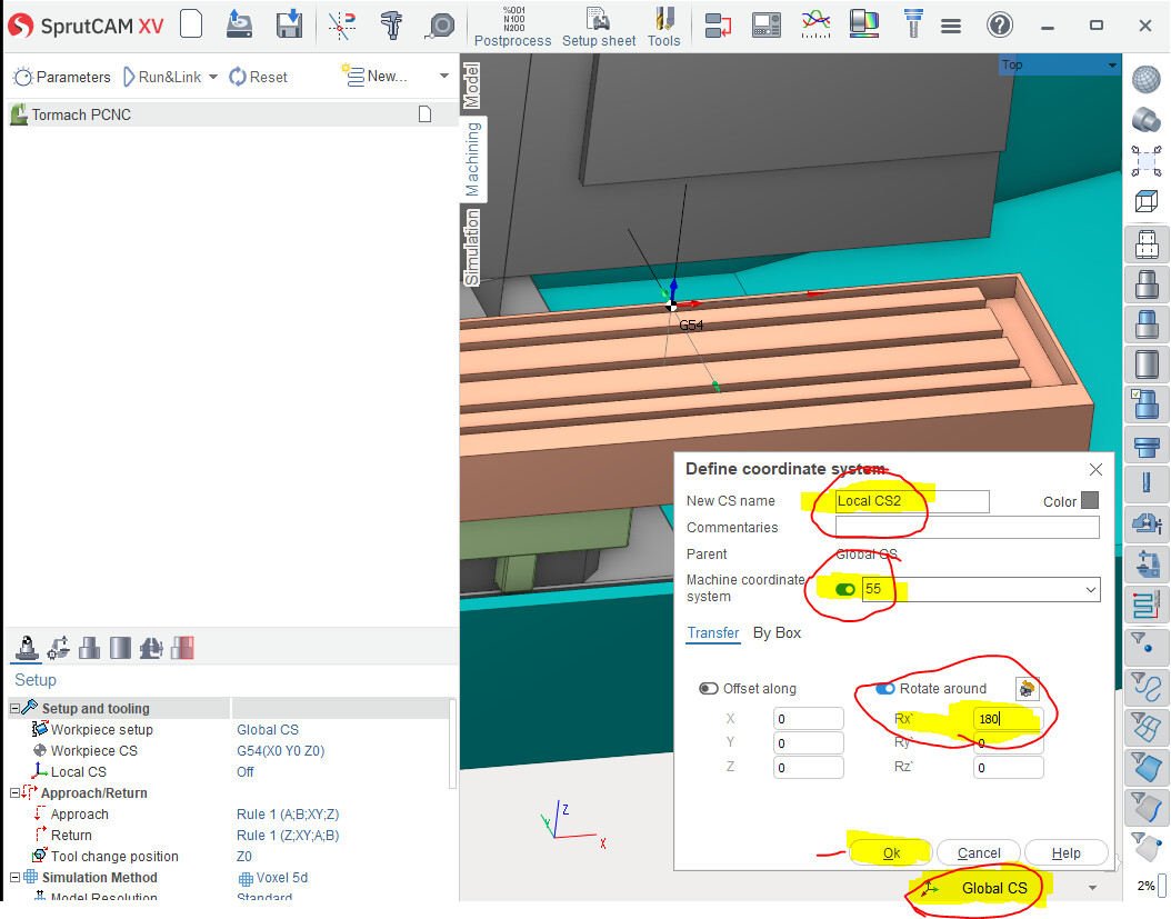
Like above the define coordinate system dialog pops up

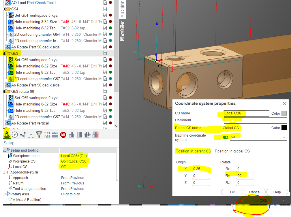
it will auto name the new one local cs2. click the machine coordinate button and set the field to g55

Then in the transfer fields below you set cs2 to a flipped coordinate by using the rotate around field of x in this case. This creates a coordinate system named local cs2 with a machine coordinate system of g55 with it rotated around the x axis of part 180 deg.
click ok button and now you have created a second coordinate system named cs2 “g55” under the global CS.

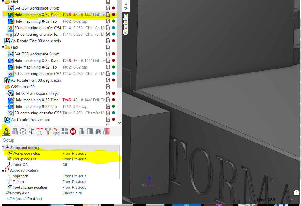
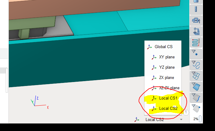
You should have 2 local coordinate systems setup now. One named cs1 that references g54

and one named cs2 that references g55 flipped 180 deg from cs1 offset or bottom center.

This details how i create coordinate systems.
I would practice using the two buttons on the tool bar to get comfortable with creating and editing and how they work together.

Note you need to select global CS each time you create a new local cs because you want all the CS you create to be under global not under another local.

it should look like this

At this point you have created two coordinates named local cs1 g54 “center top” and local cs2 g55

with cs2 flipped 180 deg on the x axis or center top flipped.

Looking at this it is super confusing to explain in a forum using pictures and text

I would practice creating coordinate systems like shown above.

it can be confusing because you can create a tree of them with dozens

I would practice editing creating local coordinates using the controls on the bottom tool bar.

Not clear I can explain this and not do a step by step from the start all the way to a part ready to machine. So many steps and clicks that are simple when you understand the process but complex when you dont