I bought an 1100S3 PCNC back in 2013 and if that machine had the 10K BT30 spindle there’s a good chance I’d still be using it and thinking about whether to upgrade. The slow TTS spindle was the weakest point, especially with an ATC, but even that was mostly tolerable in a prototype setting where 95% of your time is spent in CAD or setups and MRR is almost never a critical number.
Ultimately it is all about reducing the time and effort needed to turn an idea in your mind into a reality in your hands. The 1100 was a massive improvement in that capability compared to the DIY CNC mini-mill conversion I built a few years earlier, and I think represents a kind of local optimum for small users.
All that is what led me to the 24R - I knew I wanted a machine with a proper vacuum table and ATC, and that there is rarely such a thing as “too rigid.” Everything else was either a lot more $$$ and floor space or was optimizing for a bigger table that I didn’t want or to be a lot cheaper at the cost of being too “hobby.” Hopefully in the next week or so I will get to make its first chips.
I think you will find its easy to setup, run and get results.
Huge plus for me is It makes sweet stuff women like.
I purchased one so I could machine molds for carbon fiber parts.
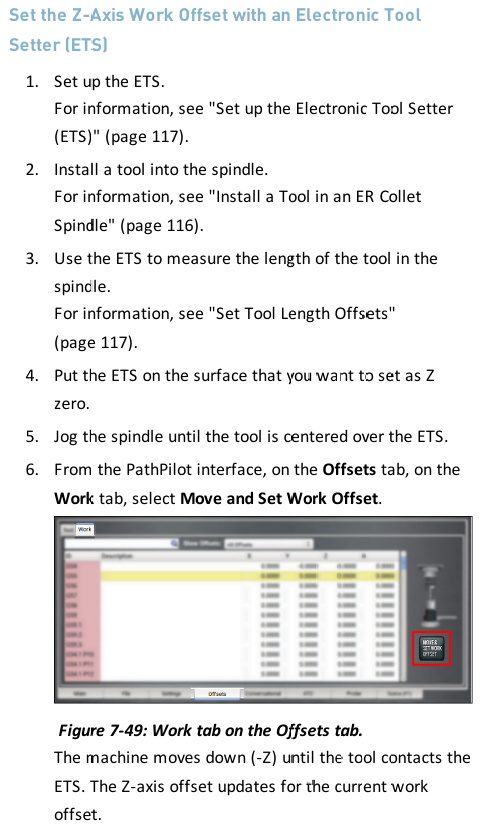
Only downside is the noise of 18k rpm cutters
Honestly, I didn’t read the whole thread, just the first few posts and then skimmed the rest. The biggest issue I noticed is that you’re putting the ETS on top of the 123 block which is not correct. The block is only there to provide an accurate reference to the table surface for the spindle to touch on. Once you’ve referenced the spindle to the table with the 123 block, you then touch off the spindle to the ETS which should be rigidly mounted to the table directly. This tells the machine the height of the ETS relative to the top of the table, which on it’s own, isn’t really relevant, but becomes important if you’re also trying to calibrate the length of a probe or haimer.
As was mentioned above, these machines do not home to exactly the same position after each power cycle. The switches used in the stepper machines are not precise so XYZ 0 can drift a few thousandths each time. On it’s own, that doesn’t matter, but since the position of the ETS is relative to G53 and G53 is relative to where the switch made contact, your tool lengths are subject to that same drift. This generally only matters if you use a tool that hasn’t previously been measured because it’s length will have been set based on a different offset compared to the other tools. All of this is why referencing the spindle to the ETS on every power cycle matters. On a router, maybe not a big deal, but still a good habit.
As for re-measuring the tools on every power cycle, that’s unnecessary. The lengths are all relative the spindle nose, which is relative to G53 Z0 and ETS position. Once the spindle nose has been referenced to the ETS, your previously measured tool lengths are all valid. That said, for precision work, I always touch off the tool when it gets loaded into the spindle. Differences in spindle temperature can alter the length by a few tenths. This is shockingly noticeable when using one tool to clear most of a surface, and following it up with another that needs to run at the same Z height (a chamfer mill following an endmill for instance). That couple of tenths can be the difference between a smooth surface and a noticeable step.
Finally, the ETS is not intended to be used for finding WCS zero, it’s meant to live in a fixed position and set your tool lengths only. The reason is that it’s trigger position is a calibrated location (see above). If you move it, it’s no longer calibrated so it’s trigger position is meaningless. At least, this is the case on the mills, the router I suppose might be different.
@Ian_Vivero thank you for the very detailed response.
Regarding the spindle height calibration, I will have to look again and see if the spindle can reach the top of the ETS–I feel like the answer was “no” which is why I ended up doing what I did but I could just as easily be mistaken and that would explain the error.
Likewise, your explanation of how you might end up with slightly different Z height references and how that could matter if you are recutting a pocket floor makes sense. I know on my 1100S3 the home switches were extremely consistent and they were mechanical. Usually the solid state ones are even more so, but who knows. I am tempted to measure the repeatability on my 24R just for my own curiosity, and will share the results if I do.
As for finding WCS Z Zero, the ETS kit for the mills specifically calls out that it can be used for that purpose. It is a different unit (4X the price) and perhaps the table flatness is another aspect of that.
It is not something I am going to lose much sleep over because for the vast majority of what I expect to do with the 24R, it will be easy enough to mostly eyeball the XYZ 0 position with sufficient accuracy. I expect the vast majority of it to be sheet processing over a spoil board so I will be working to cabinetmaker tolerances rather than machinists’.
You guys are all making to much of this setup
This machine is easy to use and does not need any goofy spindle setup if used as i explain below.
Step by step
turn machine on
home all axis
load a program that has Z work offset at top of material
fixture the material
Load a pointed chamfer tool into spindle
set that tool number in PP main screen
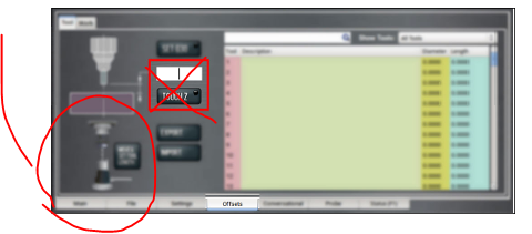
move tool over ETS and on the tool offset screen tap button to set tool height
Locate X,Y work offsets on the material as with any program
At this point you are done with all setup! the machine knows where all offsets are and you are ready to run and cut
turn on chiller and hit run
depending on program it will ask for the first tool in program and load it or ask you too
The machine will touch off on the ETS and then runs code and cuts
This process is repeated over and over for all tool in program.
Done and you can remove part
Super simple to do this all day long and no need to do any spindle setup or whatever just repeat what i did above and you can make stuff all day long.
the precision of the Z offset is based on how close you can set it with a tool and paper method.
All other offsets like x,y can be set with the same precision using a e-probe or other edge finder just like a mill.
This will get you going and as I mentioned there are more ways to skin this cat and would take pages to explain.
Bottom line this is by far the most simple CNC tool in my shop to setup and use.
you can move the ETS to top of material then set Z work offset using the below method
first load tool and set tool number
touch tool off on ETS like all normal
now move ETS to top of part and with same tool
move the spindle over the ets on top of the material and
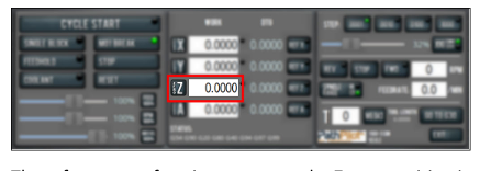
press button on this screen to set Z work offset
then move ETS back to location
And set XY work offsets and you are ready to run program
Tormach even provides a kind of location tray that you stick down to router table so you can move ETS on and off that tray and the machine always knows it is located in the correct place for g37 program ETS touch offs.
This page does explain this well. Some of the manual is confusing but this part is clear
I see now that I am late to the party but will leave my comment up anyway.
A few points of ifnterest here.
I use the ETS to touch off the top of the work piece on a regular basis. I’ll double check the manual, and make a clarification where needed.
the prox sensors on the 24r are very repeatable and I wouldn’t expect you to re touch off a tool unless you are driving for high accuracy or wear a tool down.
it sounds like you have something in the setup process out of order. If you are getting a negative tool measurement then somehow your measured tool is shorter than where PP thinks your spindle nose is.
All I know is the machine is easy to use and parts of the manual don’t apply or are misleading
The people in this thread all have CNC experience and should understand how all this works and know what to do without even thinking much.
I had my 24r setup with chiller filled and PP booted in a couple hours total from crate to ready to go
and I had code to run a cool engraving ready before the machine even shipped.
I loaded material and did exactly what I detailed above and was cutting this in less than 5 minutes
So what does Tormach say about touching off the spindle head to the ETS after each machine reset or startup?
Is this Required at all ever?
I just don’t see the need to ever do this and wonder why its even in the manual or PP interface.
I went back and looked at my setup notes and found I set the ETS height using my tool height setter and a surface plate with ets plugged in. Used that value as the ets height.
In short unless there is some reason for the conversation programming to use the value set by touching off the spindles to ets,
Every machine that has mechanical limit switches does need to rereference the spindle nose to the ETS every power cycle, due to the possible variability in the homing location. The 24R uses inductive proximity switches and the MX’s use hard stop homing so they do not need to rereference the spindle nose.
I understand home switches and the lack of accuracy or accuracy.
I don’t understand is when you home the machine. Then set value by touching off spindle. Then set the work offsets x,y,z on the work piece for the program. How is the value set in PP with the spindle touch off used in this or any program? Does it change the value you set for the Z work offsets used in programs?
In short I have used many routers all with home switches and ETS type systems
not one of them require the spindle touch off at power up to keep some sort of z accuracy.
They all work just like my 24r power up, home machine, load a tool, set tool height with ets, then move to work piece and touch tool on surface to set Z work offset. At that point the work offset is relative to the top of the ets touch off point and all accuracy depends on those two steps and not a spindle touch off step. What am i missing? How does the spindle touch off increase the accuracy of this z value?
I think the problem comes when you touch off tools in different z-ref cycles and expect the offsets to all match. If the zero reference position moves say +/-.001" between power cycles (I have no idea what the variation is) then your tools set in one cycle can be set randomly +/- .001" different in length from tools set in another cycle, yet show the same in the tool table. For some work that’s important, for others, not.
The tool lengths are all random. Each time the program calls a tool, I remove one tool from collet and install the next in a collet. It then touches that tool Off on the ets and stores that value in tool table relative to the ets. That tool can then be used to set z work offset by touching off material surface and zeroing the z work offset. At this point the z work offset is relative to the ets trigger point with any tool in the program or any program. Run program change tools and done. The results are as accurate as the leadshine drives that move the x,y,z axis using the code provided. I just dont see at any time in any program where it ever uses some value stored by touching of the spindle.
The problem for you on a router would only be creep over time. Think of it this way. If you’re doing a car steering alignment on a brand new car and the middle of the rack is 0. That is the spindle nose touch off. Let’s call this (S). Now when you load a tool and measure that number is (S+(tool1). Tool 1 is the diffenerce between 0 and the height that the tool setter sends to path pilot. Let’s say 10. That’s the tool length. So S=0 and T1=10. Let’s say this is one tooth on the steering rack. This is fine for any car for years maybe forever. But here is where it starts to matter. If you have a crash or after months of use or 100 restarts, it’s still fine for a human driven car. The problem is that if this car is driven by a computer. The computer will still only turn one tooth to make the turn that was programmed, now because of wear, bent parts or misalignment the computer uses the math that it has. Which is probably fine. Until it needs to be exact. So If the crash and spindle wear means that (S actually equals 0.9) then you run the program that missed the people by 0.1 then you have a problem.
This is why the spindle nose touch off is for. To correct any variances that build up. The more wrong the (S) is the more wrong every other calculation becomes. The good news is that spindle reference is probably the most stable variable in the whole system just because it is engineered that way.
Setting the spindle nose reference for the ETS has no interaction with the work offsets at all. If the spindle nose reference was incorrect that would result in incorrect tool lengths.
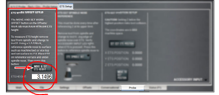
You can use the ETS to touch off the Z work offset if you want, but it’s not a commonly used feature. For that you put a tool that is premeasured in the spindle, set the ETS on top of your workpiece and probe down onto it. To do this you have to first find the height of the ETS to be subtracted from the work offset, this is done by the “ETS WORK OFFSET SETUP” column on the ETS Setup page.
No problem!
This effects the OTHER users and sales experience and was just trying to help out.
Figured I could help a 24R user by trying to explain that spindle touch off on the ETS is not required to use the 24r router and it WILL NOT EFFECT THE PRECISION EVER using the methods I explained above!
You can decide If i know what I am doing or not.
I do have a basic understanding of CAD, CAM, machine setup, use, maintenance and repair. 10k+ hours on a 1100 s3, 5k+ hours on a 24R and 2k+ hours on a 8l. Along with thousands of hours drawing and setting up parts for all three machines in CAM.