Dual VFD in a PCNC1100 for efficient RapidTurn (lathe) work then index milling on 1100 S3

Hi

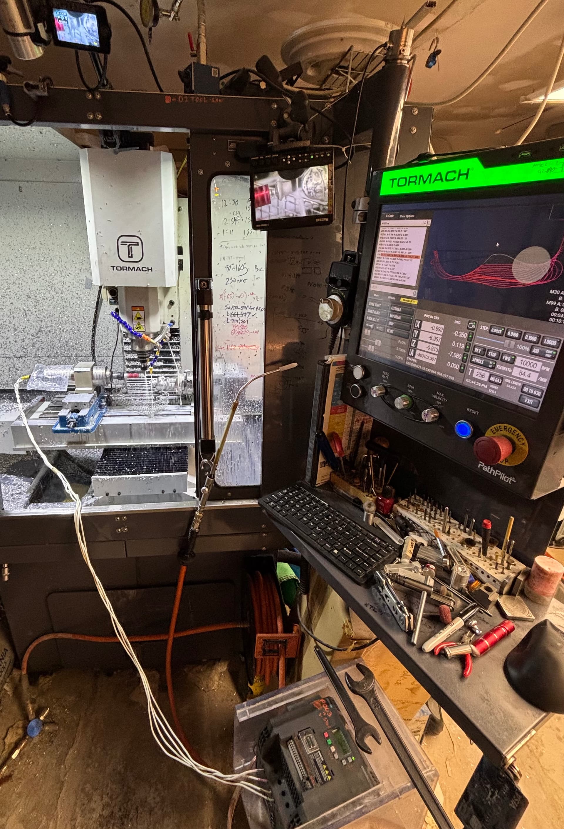
Wondering if anyone has tried to setup PathPilot (PP) to use 2 VFDs, one for the main mill spindle and the other for the RapidTurn (RT) spindle. They are different size motors so require different VFD parameter programing which is normally done via a shut down and then VFD key swap. I am wanting to avoid the shutdown to save time and preserve the part and machine coordinates.

This Tormach youtube video shows something like what we need to build starting around second 51 but without a reboot that switching milling modes forces:

CNC Machining A Chess Rook With A Tormach RapidTurn

Situation, my daughter and I are working on a project that needs lathe operations and milling operations and with the RapidTurn having the indexing every 15 degrees that makes for a perfect part holding solution after the lathe ops, but only so if we did not have to shut down to switch PathPilot and VFD parameter profiles. Note: We are not needing both modes to work at the same time, that would be a PP nightmare and is suspect the MESA card could not pull that off either. But if it’s one or the other that lowers the bar greatly! Here is what I am thinking:

HW/Electrical Solution: PCNC 1100: Add a second VFD, 1 dedicated to the Mill motor, the new one dedicated to the RapidTurn motor, so wiring would be quite simple, as I believe we only need to swap the control wires.

  1. The 3-phases to the motors are dedicated to each motor so hard wired from respective VFD.

  2. The power to the VFDs could be from the same source to each VFD. They would not run the motors simultaneously.

  3. The few control wires would need to be relayed between the two modes. With the default relay position pointing to the mill’s VFD so that mode would always work if I messed something up like a SW update.

    1. Note they would be in a static / OFF (floating) state when being switched over. Would likely still do a small ckt to ensure clean switch over if this solution works. I have a used VFD on its way here already.
  4. Note: There is a VFD reset IO that could potentially be used via USB IO relay to force it to load an alternate parameter file, but for now am going to ignore that potential option as the relays is super easy and quick.

SW solution: Have not dove into this yet and SW hacking is no longer my strong suit, so advice/support is greatly appreciated on all fronts.

1. The idea is to have the PP settings screen RapidTurn Button that switches the mode (Mill vs Lathe) continue to do so

a. Maybe even add an option to also trigger the swap via an M-Code indicating mill or RT.

2. Key need is: That PP continue to operate without issuing a reboot which is does today, thus preserving its coordinates

a. TBD what that means between a lathe and a mill, but the idea is to not have to remeasure part origin parameters which can be derived from the previous machine type mode’s part origin,

b. likely use the 4th axis coordinates to facilitate this.

c. That would require some relationship be pre-established between the mill and the RT.

3. I need to dig into why PP/PCNC needs the reboot, hoping it’s only for the VFD and would simply mean:

commenting out the reboot and

forcing the code to a past reset state in the new machine mode.

1. A code flowchart would be very helpful

b. Technically on a PCNC 770 w/RT there is no need to change over the VFD parameters as, If I am not mistaken, the rapid turn and the 770 spindles use the same type/size of motor, only the phase wires between motors would need to be relayed over, thus that machine would be cheaper easier to do this to

Any thoughts, Thanks,
E1

The break on VFD + and 0 nodes would need to be duplicated or relayed over.

The power meter on node B1 and T1 would also need to be duplicated or relayed over or simply dedicated to the mill.

You could always just wire in an external VFD and hit the go stop buttons on it. That’s what I do. I load a second spindle onto the table and have a totally separate vfd for it. It’s not as turnkey as what your talking about but I don’t have to power down either.


Depending on the vfd you can wire it up with a little control board to do rpm, go, stop, reverse and Estop without to much hassle.

Many thanks Dr Jones,

This is a very interesting idea, I love the simplicity, and was thinking it could work but then realized that I may not be able to take advantage of it as I need to use the lathe to do some ID and OD threads, so need the rotation sensor that the RapidTurn has to ensure the multiple passes of the thread cutter are all overlapping. I guess a threading capability could be implemented, but it starts to potentially need a micro controller feedback loop etc… Please correct me if I am missing something, I need to think about this some more.

Thanks again for this creative suggestion with picture, happy to see the usage model is not unique and others like yourself have tackled similar needs.

I wasn’t aware that the rapid turn could orient. That would be a lot of work to build into my setup.

FWIW. the RT doesn’t orient, it has a physical spindle lock with 15deg detents.

1 Like

Have you looked for a LinuxCNC implementation (no PP UI) that does exactly what you want (which would unfortunately have a different UI)?

Someone may have a dual spindle setup on LinuxCNC that does what you want but won’t have PP.

You probably need to go a bit under the hood of PP to learn how the UI hooks into LinuxCNC. You could connect with folks on the LinuxCNC user groups and/or those who have “hacked” your series of PCNC1100 further.

I had to dig a bit into PP and LinuxCNC at some point and while it is initially intimidating, when you look in the directory structure, it will eventually make sense. You can fork a copy/make backups of what you propose to change and go back and forth to test behaviors. You seem to be describing a limitation of the PP UI…

Thanks David, you are correct it can’t Orient as in physically set at a particular angle that is manually done with the manual indexing feature as you point out and as we plan to use to hold the part post lathe work for milling work at various 90 degree angles.

But for Dr Jones benefit, RT does have a single position sensor which I guess PP uses at a fixed RPM to know when to engage/re-engage the cutter to perform repeated passes on a single thread as can be seen in this video at just past the 16minute mark:

Making a threaded adapter on the Tormach RapidTurn

Thanks for clarifying Davie

PS from the electricals perspective the dual VDF solution I proposed looks easy with a hand full of options. From a quick read last night of the 2 VFD docs compared to the Tormach Controller/VFD wiring schematic: I am inferring the VFD PR05 config is likely AI.Pr with the Pr (predefined speeds) part is being ignored and the VFD T2 pin controlling speed via a reference current, which means it must be relayed between.

Can’t be the red modes for various reasons, and unlikely to be the yellow modes. Will have to dig up the parameters file from the VFD stick to be sure of the mode, which I presume must be the same for the RT vs. Mill modes.

Hi Ashraf,

Thanks for your insightful suggestions. I have not looked into LinuxCNC code, wanted to keep PP, but you have revived a old memory that PP was built on top of LinuxCNC so yes this is a direction I should explore.

I did post the first rev of this thread in LinuxCNC.org under mill but no response from anyone so far, but it’s not yet even 2 days.

Dual VFD in a PCNC1100 for efficient rapidturn (lathe) work then index milling - LinuxCNC

Thanks for the encouragement on the PP directory structure, I will have to tackle this now and this motivates me with a logical direction as to where to start and on the SW front.