Hi,
This seems like it should be an easy fix but isn’t working. I am machining the 1st side of a rectangular part 2.75" X 2.25". After running the part it is about .006 oversize. In the offsets page I reduced the cutter diameter .003 reduced the feed rate in half and reran that operation. It cleaned the pass up but didn’t really change the size. Repeated dropping the cutter size another .003 no change.
Is there a different place to change cutter compensation? Don’t want to remove the part since I can rerun it in place.
Art
What are you selecting for compensation type in your CAM?
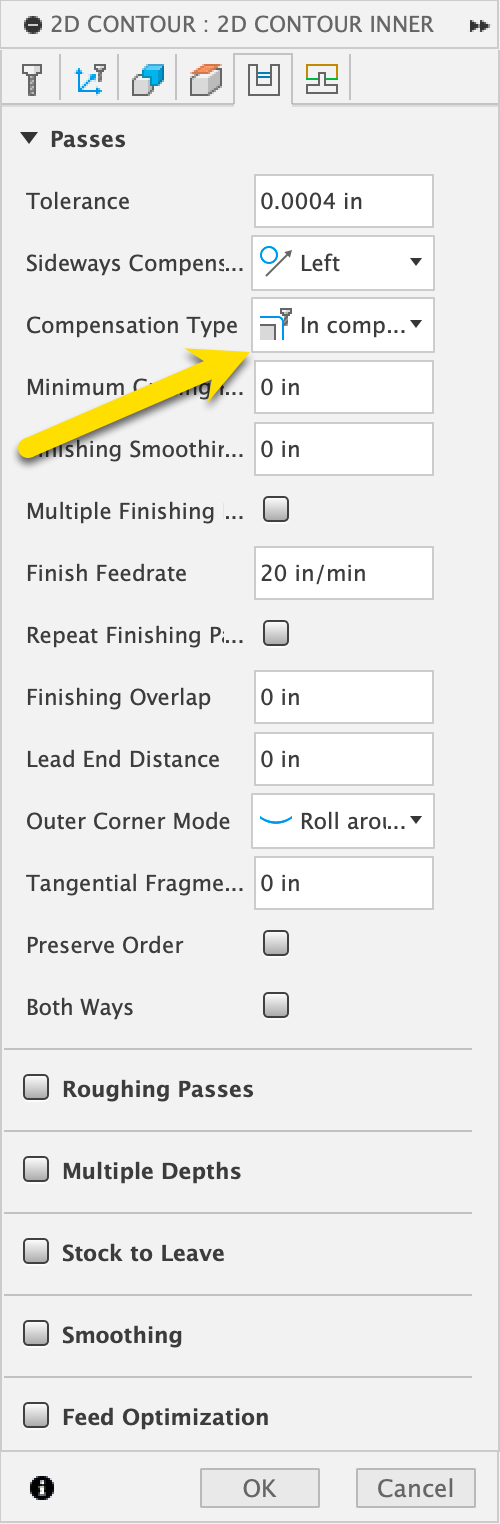
For this, I would adjust the stock to leave a negative number, but sneak up on it. I think you’ll find the cutter dia in PP could be zero, and it wouldn’t matter if you’re using it “in computer” for the compensation type.
1 Like
Scott,
Thanks for replying. I had checked the diameter with a micrometer and entered that into the CAM. If I set the diameter smaller in CAM rather than doing that in PathPilot, would I get the same result.
As I understand your above suggestion I would change my radial stock to a negative number leaving everything else the same
Art
1 Like
Yes the diameter in the tool table in PP does nothing unless you are using in control as your compensation type. If your part ends up too big, you could do it a few ways
- go into your design and make it smaller by the error
- go into cam and assuming you are using “in computer” as your compensation type put a radial stock to leave of -.003 if that’s your error
- if you’re using “wear” compensation in the compensation type you can put that in the tool table under wear comp.
What version of pathpilot and what CAM software are you using? Also what compensation type do you have selected?
I recently replaced the control computer and it came with PP 2.12.1 I am using SprutCam version 15.
I don’t know sprut cam but I assume you can choose between in “control”, “computer” or “wear” which do you have selected?
I found this in the Sprutcam documentation.
CAM-system can generate a trajectory with tool radius correction. On the “Lead In/Lead Out” page is a panel where you can enable the use of correction, as well as to select the types of compensation switch lines.
There are 5 different types of the correction:
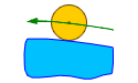
- Computer----. In this case, the CAM-system itself calculates the trajectory with the size of the selected tool. In the program is generated a trajectory for the tool center. Correction turn on and of commands does not appear. This does not allow the operator to affect the correction at the machining time. However, the CAM-system when calculating the toolpath can correctly handle bad cases and remove the loops. That pretty much guarantee the accuracy of the trajectory and the absence of gouges. This type is installed by default.
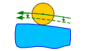
- NC control----. In this case, the trajectory calculation is made without taking into account tool radius. In the NC-program displays a contour of the part, as well as the turn on and off compensation commands of the appropriate sign. This allows the operator to adjust the trajectory, taking into account tool radius actually used at the machining time. In the simulation mode to simulate the behavior of CNC uses the correction value is equal to the radius of the tool.

- Wear. ----The calculation is made given the size of the tool, as with options . But in the NC-program will also appear the compensation switch commands. Correction is directed towards the part. This allows the operator to compensate the tool wear, setting the value of correction as the difference between the source tool radius and the actually used tool radius. In the simulation mode for emulating the behavior of CNC the zero correction value is used.
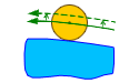
- Reverse wear—. Similarly type, but the sign of the correction is opposite (directed from the part).
2 Likes
When I was using Fusion the PathPIlot control did not seem to work when I used in control comp. I didn’t find out why and I use mostly conversational now. That said when I change tool diameter in conversational I have to reload the program due to PathPilot plotting the actual tool path in stead of profile path.
The cutter comp works fine when I manually program the actual profile and use comp.
Dave
I use Fusion and cutter comp and it works as expected… as long as I remember to turn it on.
Cutter diameter in PP not doing anything is a classic sign for me it’s not turned on for that toolpath-- Fusion defaults to ‘in computer’ (ie: ignore PP diameter) plus doesn’t have it in some toolpaths like adaptive clearing.
1 Like
I liked fusion but quit using it after all the rapids were reduced to g01 speed for hobby use. So I never explored why it wasn’t working for me.
Since I learned on autocad it was an easy transition.
Using Alibre now and it came with Meshcam. Not near as good but works. Most of the tutorials are for routers.
Dave
I’ve been using Alibre as well, never used anything but SprutCam steep enough learning curve I don’t want to switch. Just out of curiosity in Fusion can you edit the post and change the G01 to a G0?
Art
I don’t remember if fusion changed to all g01 or just limited the speed of G00 to the highest G01 speed. With a small program it wouldn’t be difficult with notepad. But using an adaptive toolpath would be a lot of editing.
Dave
That small program has been avaible for quite some time:
TimPaterson/Fusion360-Batch-Post: Fusion add-in to post all CAM setups at once, optionally dividing them into folders. Also fixes some of the limitations of Fusion for Personal Use, such as allowing tool changes.
1 Like
I use Inventor CAM on a PCNC 1100 . By choosing “In Control” or “Wear” the CAM output uses cutter comp G41, G42 and reads the cutter diameter from the tool table.
If you are trying to sneak up on a dimension, this is a great way to go because you just change the cutter size and rerun that part of the program. The CAD model stays accurate and no CAM revisions or reposting is needed.
“In Control” uses the size of the cutter i.e. .500, .496 etc. This will sometimes lead to PathPilot erroring out at the compensation line when loading, especially in small pockets because the internal parameters think it won’t fit, even though the CAM runs it fine. To avoid this, use “Wear” and the number in the tool table is the deviation from nominal size of the cutter, i.e. 0. , -.004, etc.
Often I am only making one of something or repairing an item, so there’s no option for setup parts. I will set my cutter size oversize i.e. .510 or +.010 for a 1/2" cutter, then measure and adjust the tool table . Note the second pass will take a little heavier cut if your finish pass was aggressive (like the amount you changed plus a spring pass) but subsequent passes will only take the reduction.
So if you were .010 oversize and you reduce the cutter by .005 the next pass will be .003 oversize (.007 cut). A third pass reduced by .003 will be truer to the change and put you right on size.
I have been busy recently but am intending to run the program with the diameter and then creep up on it. Had a family reunion last weekend, cought some cold. Plan to be at a local steam and gas show this weekend. I’ll give it a shot next week.
Art
So much for plans, appears our family reunion last weekend was a COVID spreader event. Me and my wife both tested positive today. So suddenly an open weekend. I’ll see what I can get done in the shop.
1 Like
Where I come from we call that a “yeah/boo” yeah! More shop time!
Boo… covid.
Yeah Davie, yesterday after testing I was quite disappointed. The badger steam and gas show was one of two engine shows I had planned to attend this year. Soon got over what I couldn’t change, and planned what I could do. Keep running into problems with cam. Ain’t doing what I expect. Well there’s always tomorrow.
Art