I recently took an online knife making class. In this class the knife blade is fastened to the fixture with 1/4” shoulder bolts. This of course requires a 1/4” precision hole in the stainless-steel knife blade and fixture to properly locate the blade. These precision holes were bored and reamed to final size. For production purposes, this boring/reaming approach makes sense. As I hobbyist with a new mill that holds tight tolerances, I would prefer to bore these holes and skip the reaming process.
Previously, when I want to creep up on a precise hole size, I have adjusted the stock to leave in Fusion to iterate to a specific size. I have never used “Wear” (for cutter compensation) but it seems like a better way to bore a hole to a precise size without reposting gcode. Just a few questions:
- If I bore a test pilot hole, and the hole is too small, am I correct that I add a negative number for the diameter wear figure in Path Pilot to make the hole larger?
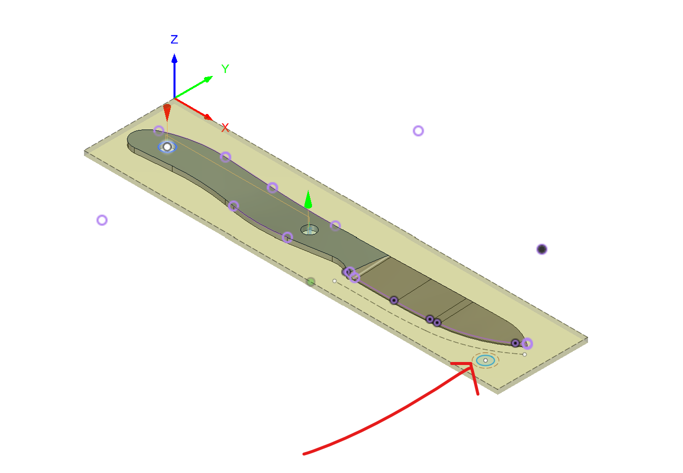
- The location of one of the holes that needs to be bored in the knife blade stock is located by a sketch so there is no hole to select. Even if I select this sketch in Fusion (geometry tab), the “Bore” tool path will not bore it. I used a 2D contour command to bore this hole instead. Is there any way to use the Bore toolpath? See image below.
- The boring tool path used in this lesson uses a 3/16” end mill and has a pitch of .039”. I have never machined stainless steel before, but this is about an 11.2-degree ramp angle. Does this make sense?
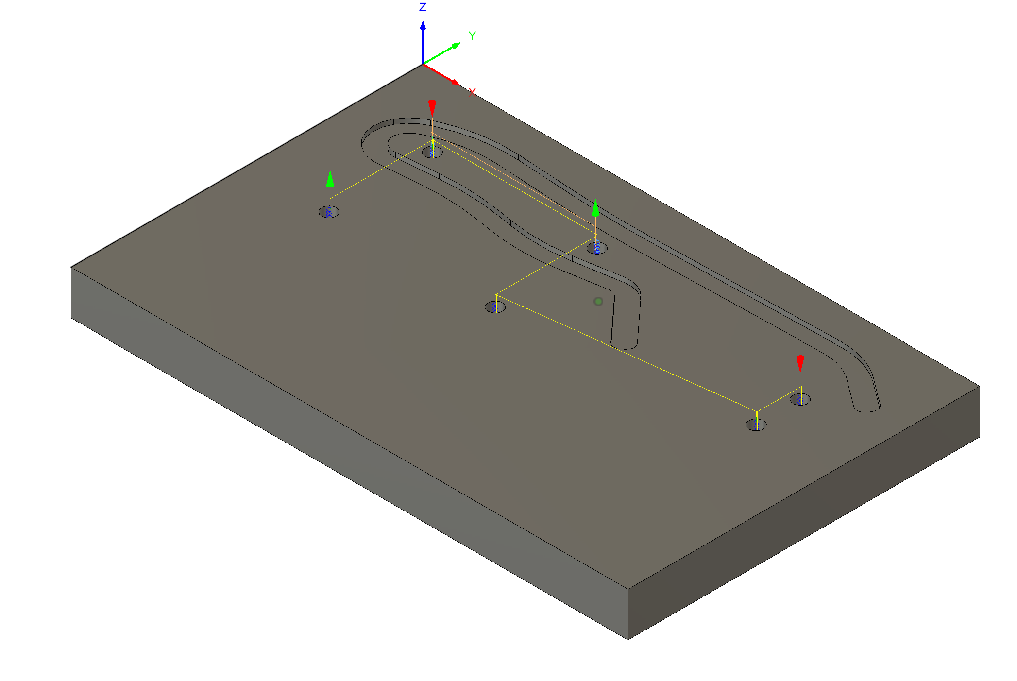
- Lastly, the holes in the fixture are bored to 1/4" and tapped with 10-24 threads. In the online class they thread milled the holes. Is there any reason I can’t rigid tap them?
BLADE STOCK:
FIXTURE:
Fusion File:
CAM NWPairng.f3z (1.2 MB)
I believe that looks more like a 1.2 degree ramp angle, yes you are right on changing the diameter with a negative number in the offset page, as long as wear is selected in fusion360 as well, fusion also has a inverse wear option, that would make it so you would input a positive wear value instead of a negative, but ive never used it that way, not sure if that would be making the hole smaller then or not, since i think of it as you have a .187 dia em, your hole come out at .247, so you need to do a -.003 wear input, since the smaller the tool the more offset the control has to input into the code to make the hole the correct size, the tool didnt shrink by .003, but your just telling the controller it did so it offsets the toolpath more.
ive always heard that roll tapping/form taps were better for stainless but whatever works best for you.
Drill and ream. Spotting bit. Carbide drill for longevity. Might hit diam right on.
Thanks for all the great feedback. I had no idea that value entered into PP was a diameter value… really good to know! I have not made lots of fixtures before, but I want the shoulder bolts to fit as tight as possible into the bore in the knife stock, so I think the best approach is to machine a test hole and iterate so the shoulder bolt just drops in.
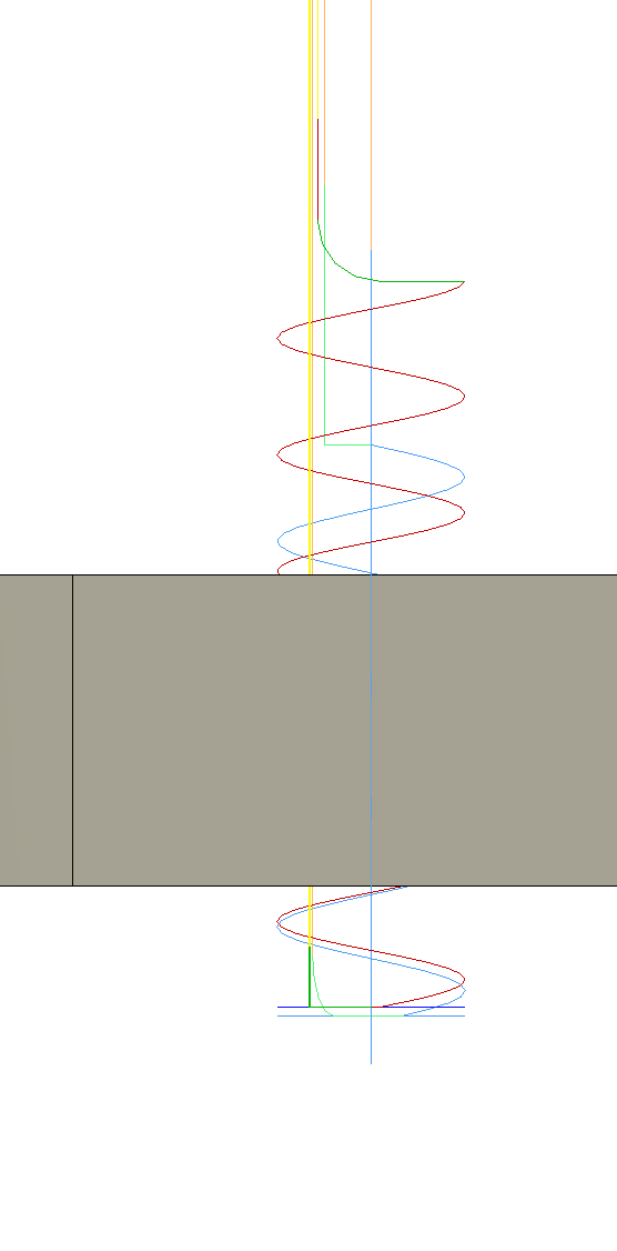
When I could not get the boring tool path to use the sketch geometry, I used a contour tool path. This is when I noticed that the tool path created in the online lesson had a pitch of .039 in. I calculated this to be the about same as an 11 degree ramp angle. I will check with the tooling mfg to get the correct ramp angle (see below).
I am running a 1500MX. The reason I asked about thread milling vs rigid tapping was just to see if there was any reason you would favor thread mill instead of rigid tapping when you use shoulder bolts for a fixture. The fixture will be 6061 so rigid tapping is no problem.
One new question:
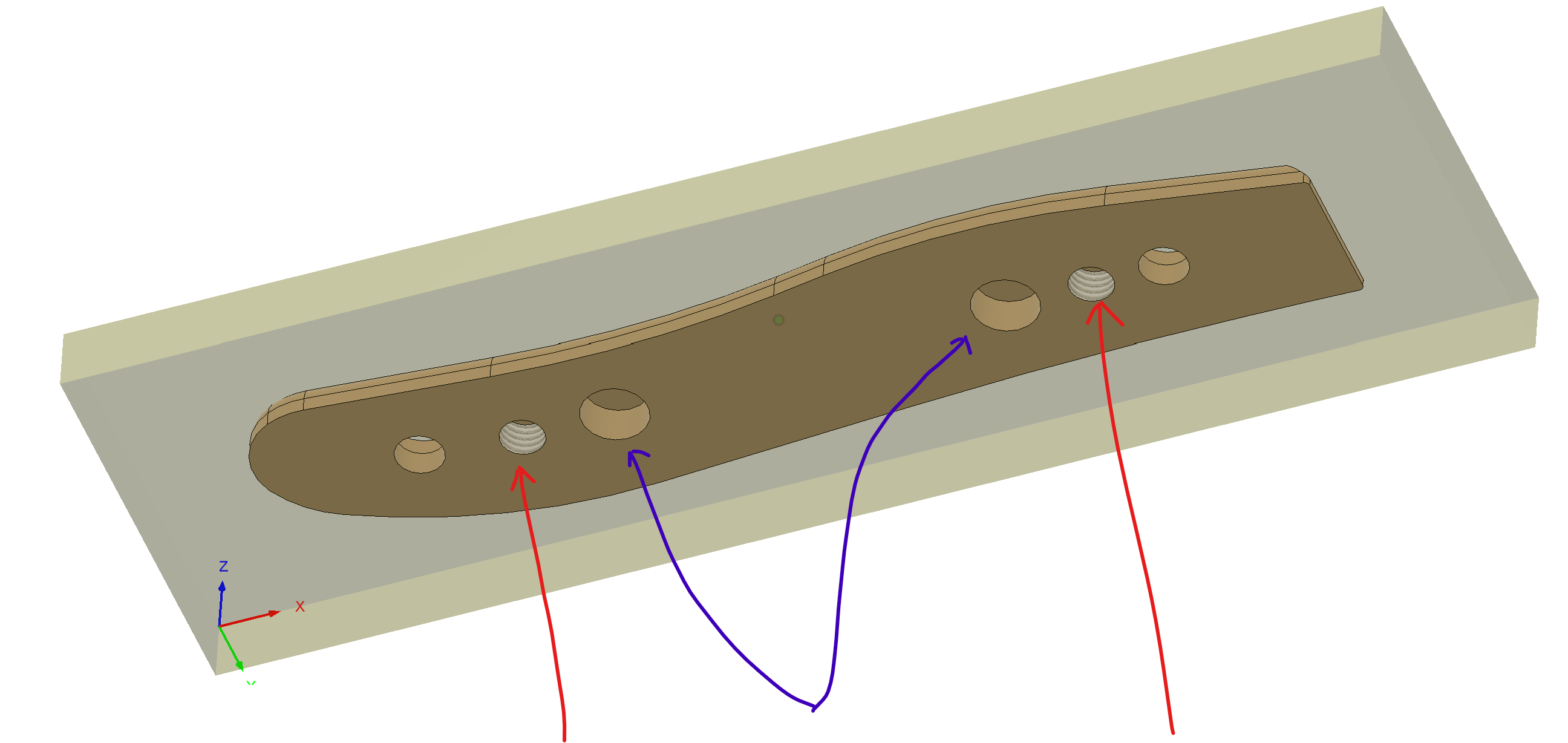
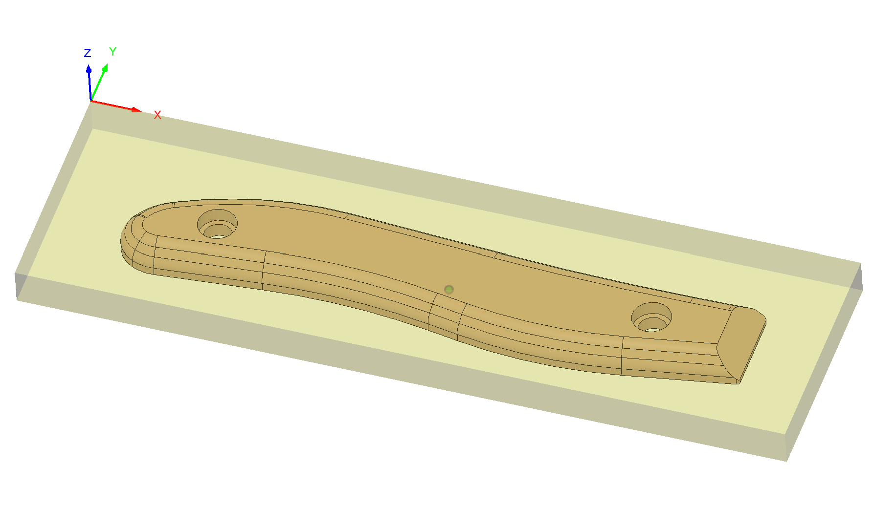
I plan on machining the knife handles sitting on a pedestal to raise them up so the ball end mill can reach. I plan on using m5 screws screwed into the bottom of the handles (red arrows) and registration pins to locate the knife handles (blue arrows). The registration pins shown are 1/4" diameter. Do you think I can safely use smaller diameter pins?
Knife handle - bottom view:
Knife handle - top view:
Thanks for all the feedback… Richard
Ramp angle bore toolpath with .039 pitch vs contour toolpath with 11-degree ramp: