Using Fusion 360 with the Tormach pcnc440 and the Arc4 axis. Fusion has been generating buggy code, from a sudden path across the object and crashing into the arc4 chuck to a simple ellipse shape pocket being completely faced instead of the pocket being cut.
Is it just me? Keep trying different operations from Wrap operations to Multi Axis operations.
Anyone else experiencing these issues?
Haven’t done any multi-axis stuff for a few update cycles but I’ve never had issues like that. Can you post your file?
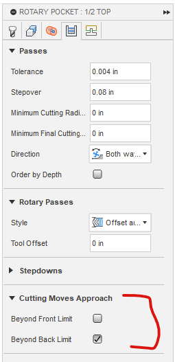
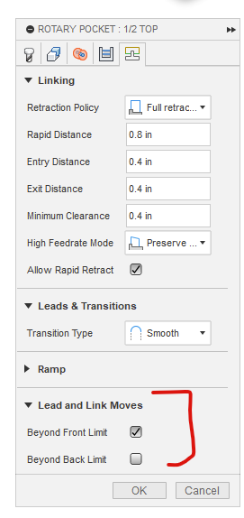
I fought fusion for a long time to make this Santa with a microarc4 on a 770m. Fusion kept doing goofy stuff like winging into the chuck jaws. I eventually figured out that fusion isn’t as smart as I thought and I had to really pay attention to the front and back definitions and where the tool can go further than the front or back for lead in moves. Sometimes I would have to change the setting then change it back and it would magically fix it. I’ll dig into it next time I have fusion open, and post more details about what I did.
I am setting this up to run again and plan to do it completely different this time. I will set up a few indexed moves to remove the extra material then use a rotary tool path to surface the part.
@Don_Gillard These two sections cleared up a lot of my mishaps once I dug into them a little. I never did figure how the proper way to establish front and back of part other than just to go with what Fusion decided and work from there.
Any tips on zeroing the Arc4. It seems to loose its g54 easily, and no real way to accurately re zero it. My latest file after creating an A-0, the g-code didn’t bother to rotate the arc for the operation (ie it was supposed to rotate 45deg before starting to machine.
I’m not following your question. When I made that Santa I milled a flat in the stock at A0 but that was in case I had a power failure or some other issue while cutting. My thought was that I could run a dial indicator across the flat to true A0 after referencing the machine.
The micro arc doesn’t have any kind of feedback encoder that I’m aware of. All I ever do is make sure the A axis is rotated back to 0 before I power down the machine. When I power it back up and reference everything, the A doesn’t move, and simply gets set to 0 while the other three all move through their reference routines.
To set the 0 initially, I have a couple methods depending on my setup. If the exact orientation of the material or the workholding isn’t critical, I just set it where ever things look sorta level. In some cases I use my phone as a rough level just to get close enough.
For critical applications, I use a dial indicator across the vise or material and adjust A until the surface is parallel to the Y axis travel.
If you’re trying to set zero in X Y and Z, this can be a bit more difficult depending on where the microarc is mounted to your table but the easiest method I’ve used is putting a small piece of scrap in the axis and take a cut on one side to create a flat. Rotate the part 180 and take another cut in the same position (make sure you’re removing material in both cuts). Measure the resulting part, divide by 2, then add the tool radius to get your position in Y. For Z, do the same thing but don’t add the tool radius. X is arbitrary depending on your setup and program but can usually just be touched off with a probe or edge finder.
That position will have to be re-established after every machine power cycle because homing isn’t precise. I haven’t done it yet but my intention is to create a table mounted gage block that is a known distance and height from the centerline of the A axis so I can just touch off on that to re-establish my A position. Since I have a fixture plate, I can get away with this being a non-permanent setup. If you’re using the T-slots, you might consider something similar that references off the microarc baseplate in some way.
Thank you, that does help


