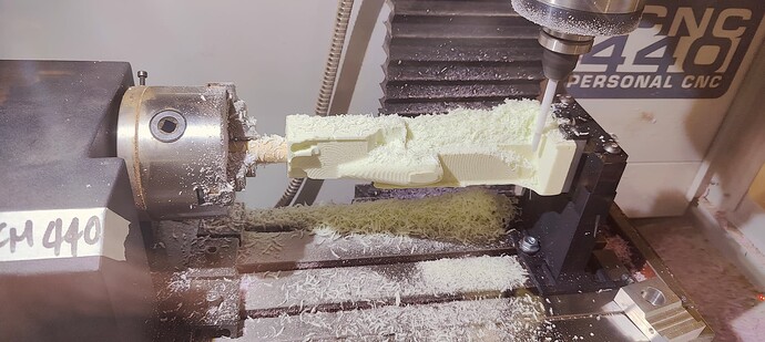
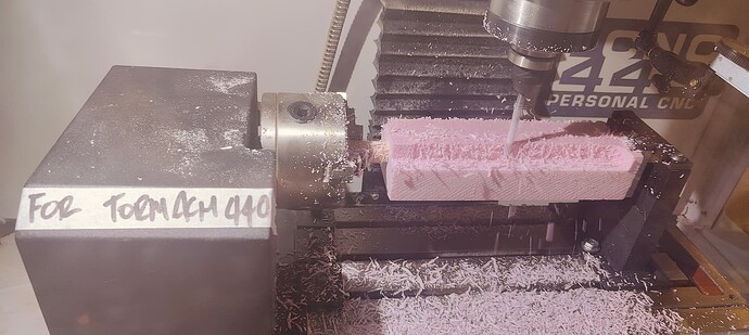
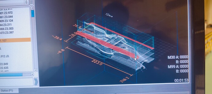
Have installed a rotary A axis on the 440 and am currently using Fusion 360 to create F1 in Schools cars.
In this example, I set the WCS (correctly) and create tool paths for the 4 faces of the model.
Z as Z, Z as Y, Z as -Z and Z as -Y.
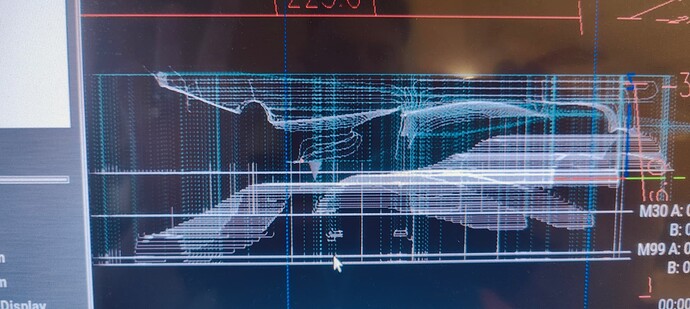
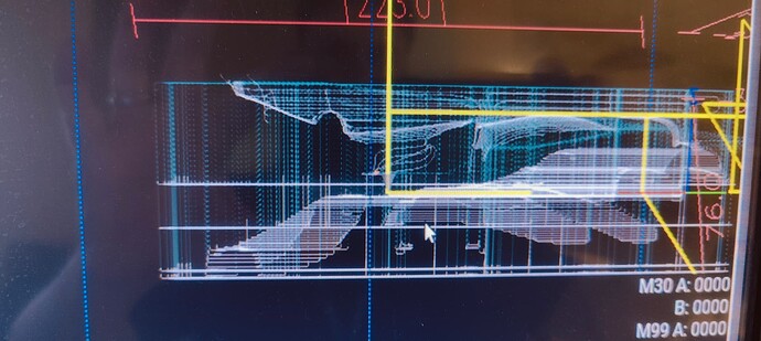
The Z as Y always seems to be upside down in PathPilot.
The initial face is cut perfectly and the rotary turn exactly 90degs. But the toolpath is upside down…
I’m using the built in NC Tormach Post Processor 440 Rotary (X) within Fusion.
Are you saying that the toolpath or preview is wrong?
To clarify, I am asking which scenario your are referring to:
- the part is being cut correctly but the preview is incorrect
- the preview is showing the tool path but the tool path is incorrect
If the second is true, can you share your fusion file?
So the preview and the cut are in sync, so it has to be a fusion issue I guess. If I zero the Y and Z in Pp at different points, the inverted tool path moves away from the other 3 tool paths.
(It’s so odd, I can’t even describe it)
I’ll post the code and Fusion file here in about 12 or so hours (night-time here)
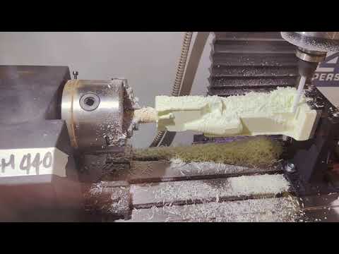
I actually recorded a tutorial thinking that it would work, this is the exact work flow.
Think I’ve fixed it, but it seems wrong.
By switching the location of the rotary in PP I get the tool paths to align but of course the rotation is backwards so it’s produces the same error.
However, telling Fusion that the rotary is in a -X orientation, the model is correct and the output is correct…
Fusion error I guess?
FWIW switching the orientation of the 4th axis within pp will only change the tool path preview and not affect the cutting operation of the machine.
Correct, which lead me to changing the Fusion orientation instead and it worked…
I’m guessing we switched the wires somewhere, the rotary was taken from scrap complete with the driver box, must have been originally in reverse or something.
