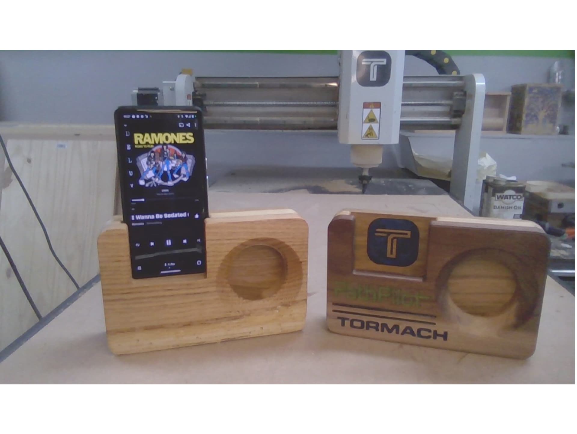
Live Project: Acoustic Phone Amplifier Project
COMPETENCIES
• Machine Start Up
• File Transfer
• Stock Set Up
• Tool Length Set Up
• Tool Geometry — Ball vs Flat
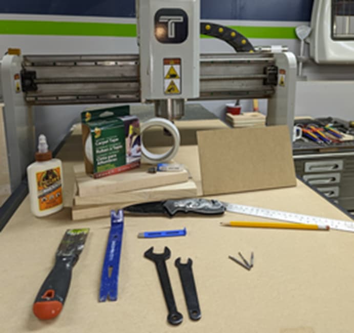
MATERIALS
• 1 — 8.5 X 5.5 X .375” MDF Board (Sacrificial Plate)
• 3 — 8.5 X 5.5 X .75” Wood/MDF (Project Material)
• Duck Brand Indoor/Outdoor Carpet Tape
• Wood Glue
• Straight Edge
• Pencil
• Knife
• Rigid Scraper/mini-pry bars
• xsTECH Spindle Wrenches
• Paintbrush/Vacuum for clearing chips
• 1 — ER11 Collet, 4 mm
o PN 39174 — Spiral Up-Cut Plunge End Mill: 4 mm x 12 mm x 4 mm x 50 mm
o PN 39166 — Straight Ball Nose End Mill: 4 mm x 25 mm x 4 mm x 50 mm
o Engraving V bit or .5-1mm ball end mill for customizations (Must fit ER11)
• USB Drive or Wifi Connection to PathPilot Hub and Machine
Amp Files:
Amp_Back_T1.nc (8.8 KB)
Amp_Center_T1.nc (27.1 KB)
Amp_Face_OP1_T1.nc (18.9 KB)
Amp_Face_Op2_T2.nc (944.3 KB)
xsTECH Start Up Procedure:
*If this is a brand new router, the PathPilot screen will display your startup prompts including serial number registration. Follow these prompts as displayed on the screen.
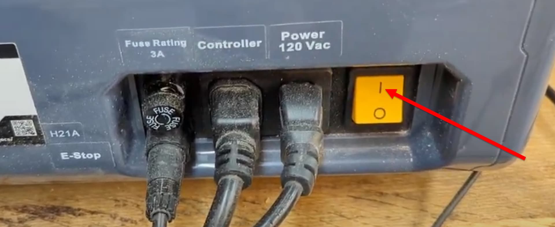
Power up your xsTECH by flipping the switch on the back bottom right corner of the machine to the up (I) position.
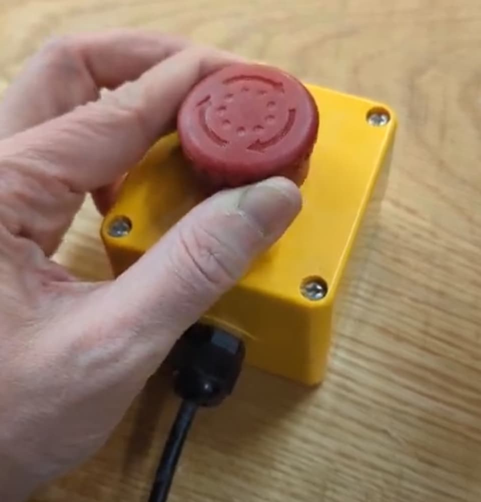
Release the E-Stop by turning the red button clockwise until it pops up.
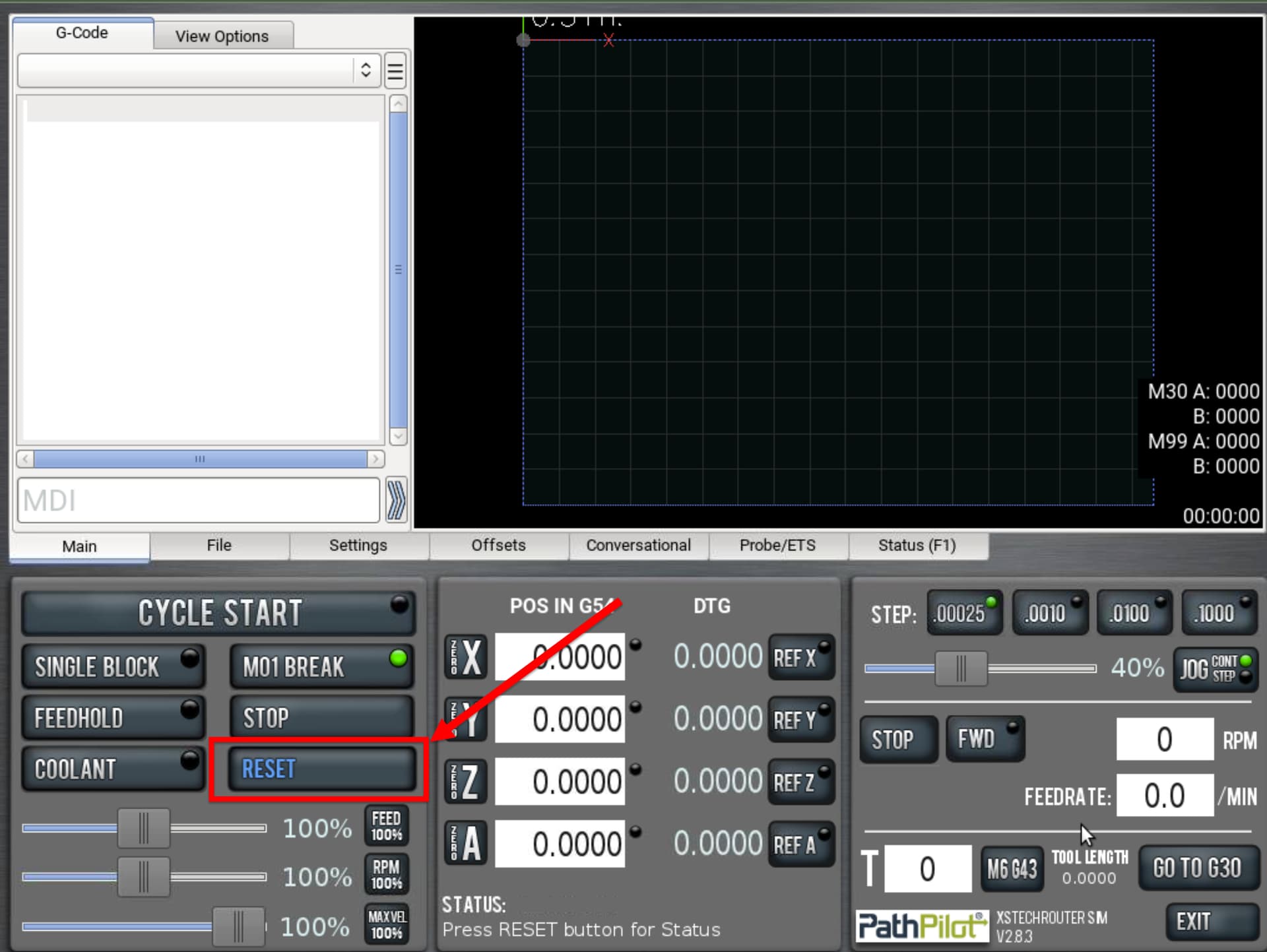
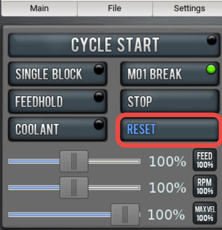
Once the PathPilot screen powers up to the main screen, you should see a blinking blue reset button. Press this button to complete the machine power up process.
Referencing your Router
The stepper motors of your xsTECH do not have positional memory, which means — simply — that when you power up the mill, the PathPilot Controller and the stepper motors do not know where they are in reference to one another. Inside of your unit, there are plunger style switches. When you select the REF X, REF Y & REF Z buttons, the steppers know to keep moving in the homing direction until they bump the three switches. The position of the axis at this ‘bump point’ is now the machine ‘home’ position that the control will use in its calculations on table, spindle and gantry position until the next power down/power up sequence (when it will lose its memory again).
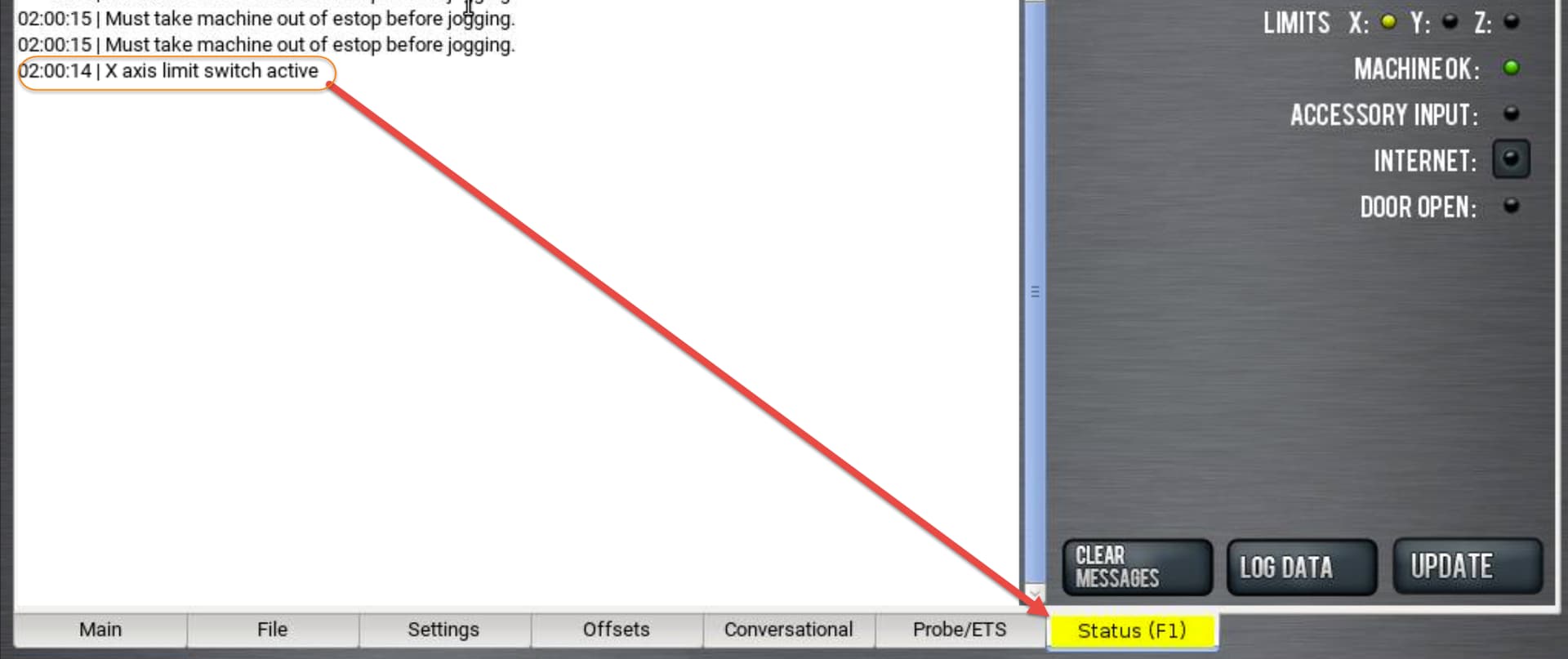
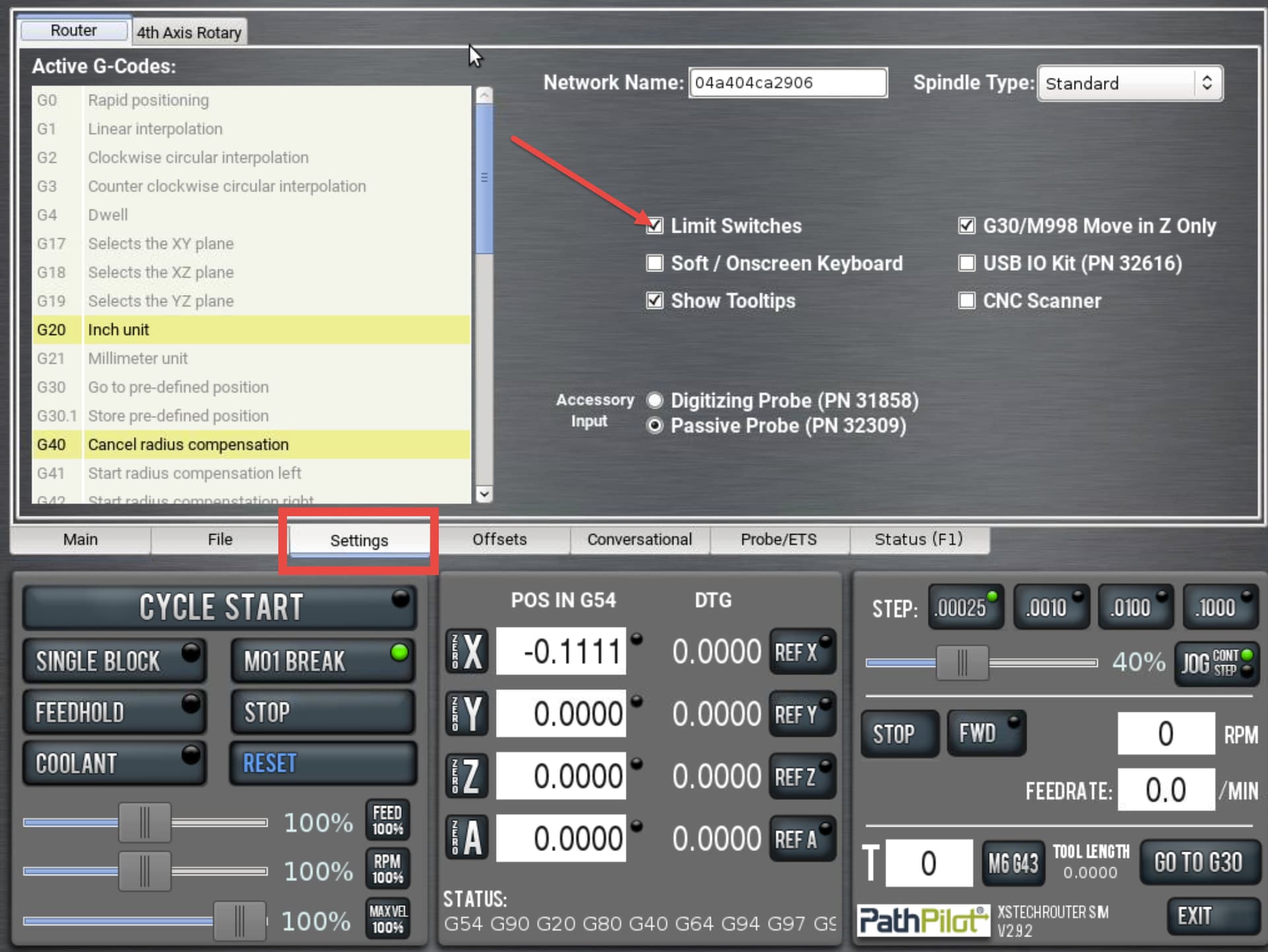
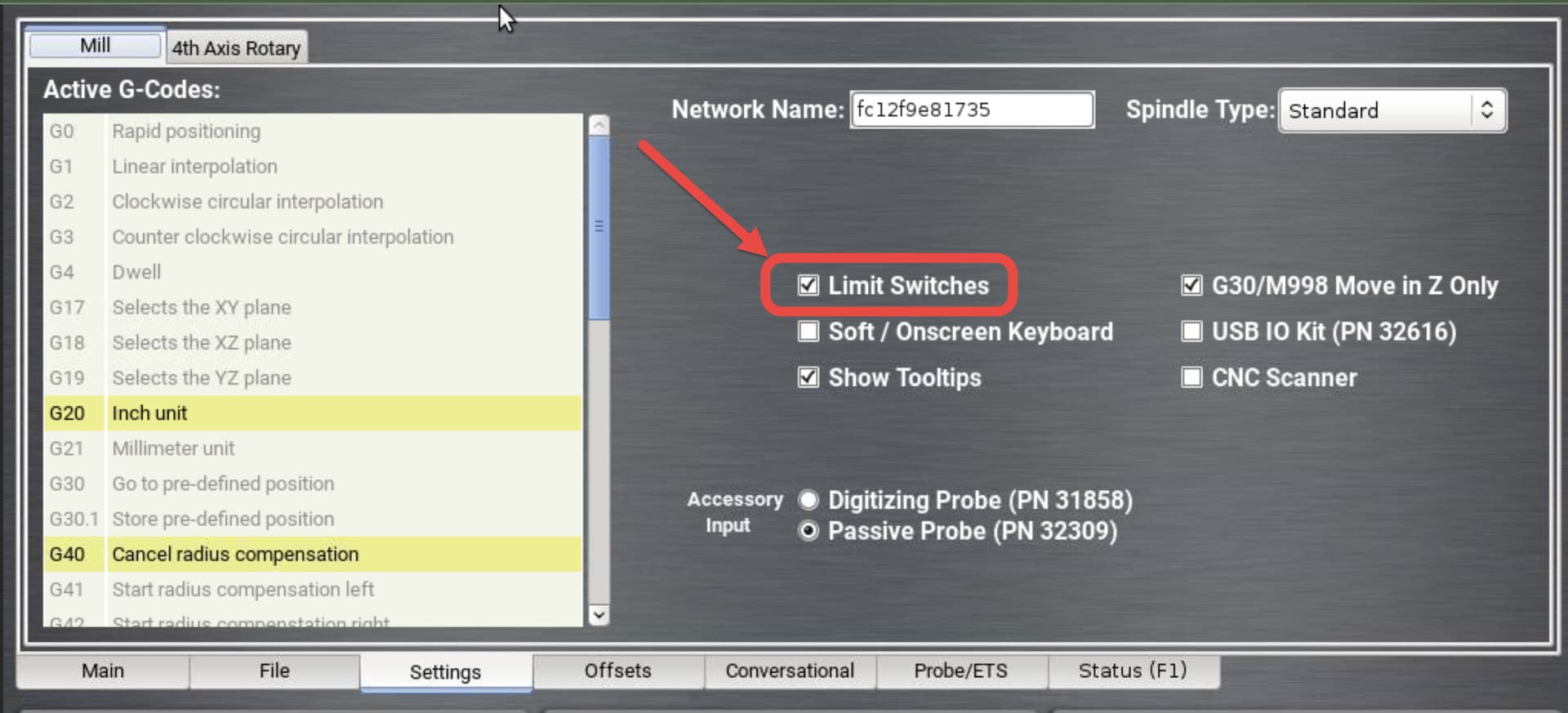
On occasion, when transporting the router or when hitting the switch at a rapid speed, your control will display a ‘limit switch’ error. The Status Tab will turn yellow and PathPilot will note an axis (X, Y, Z) and limit switch fault. If this occurs, simply go to the settings tab, unselect the limit switch option, and then press the reset button. Using the hand shuttle, jog the table, gantry and spindle to a neutral position (at least an inch away from each extreme edge of the axis travel). Then go back into the settings tab and reselect the limit switch option. Now you may re-reference all three axes again.
If Limit Switch becomes active, follow these steps:
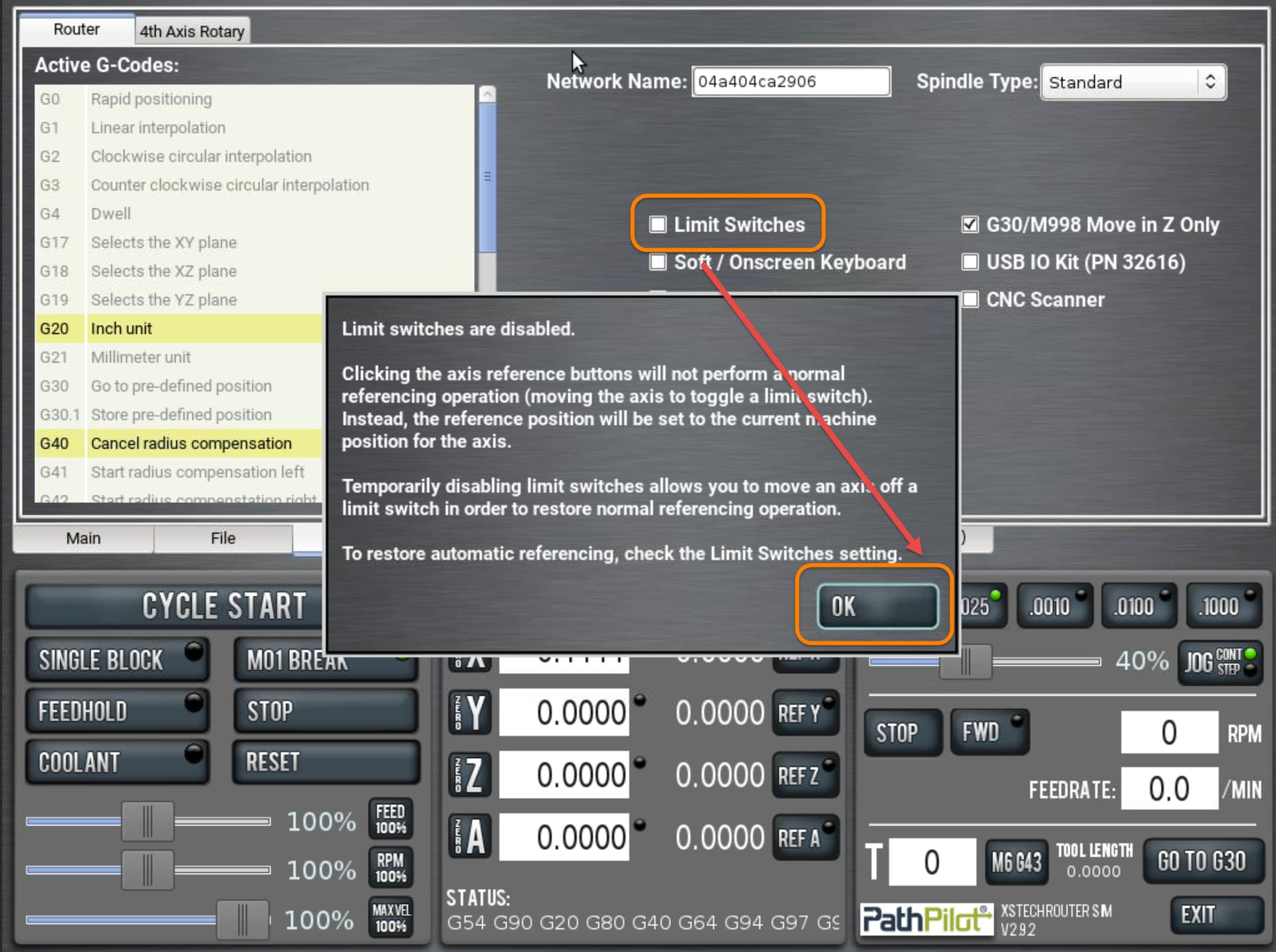
Uncheck the Limit Switches option in the Settings tab, then select OK in warning:
Hit the blinking blue Reset button.
Using the hand shuttle, slowly move the table, gantry and spindle away from either extreme of their travel (about an inch minimum).
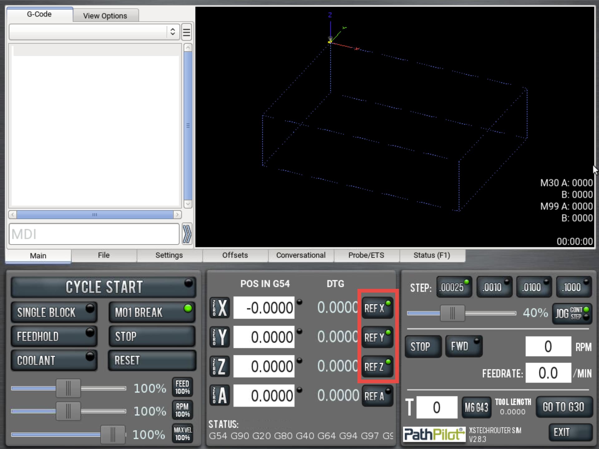
Once you are off the limit switches, check the limit switches box in the settings tab so that we can complete the homing sequence.
Press Ref Z, Ref Y and Ref X on the main control screen.
Terminology
Machine Reference (Home) This machine position is the plunger point of the reference (home) switch. The toggle point where the axis activates the switch becomes the machine home position during the reference sequence.
Work Envelope The usable work space in the machine in which a machining operation can be performed between the machines extreme limits.
Machine Travel The distance from limit to limit on each axis. For example, the travel of an xsTECH is 8.8” in X, 6.5” in Y and 2.5” in Z. The space within these limits make up the machine work envelope and is graphically displayed in PathPilot as the blue box that appears on the main screen.
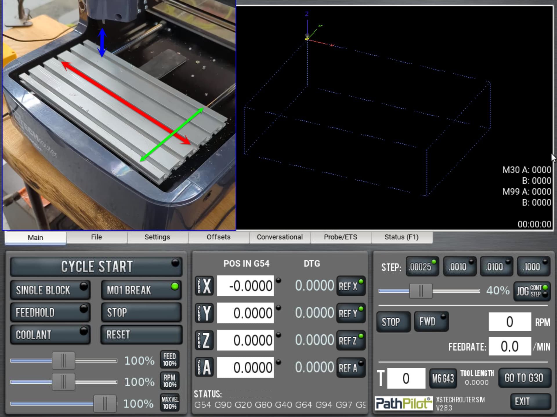
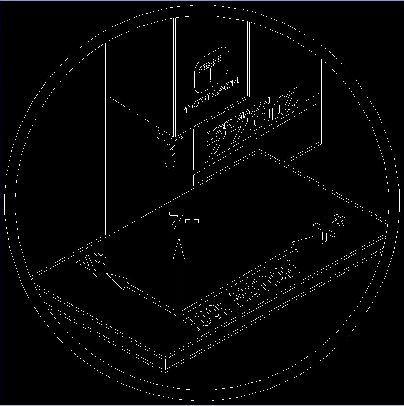
The axis motion on your router or mill is defined by the Cartesian Coordinate System. The directions for each axis (positive and negative) are defined by tool motion. The location of the coordinates within your machine as well as your program are determined by your Work Coordinate System (WCS) and origin. The origin is the defined X0Y0Z0 point on your program as well as part (stock). The Work Coordinate System allows you to corelate the physical stock location in the machine to the program that you will be using to machine your part.
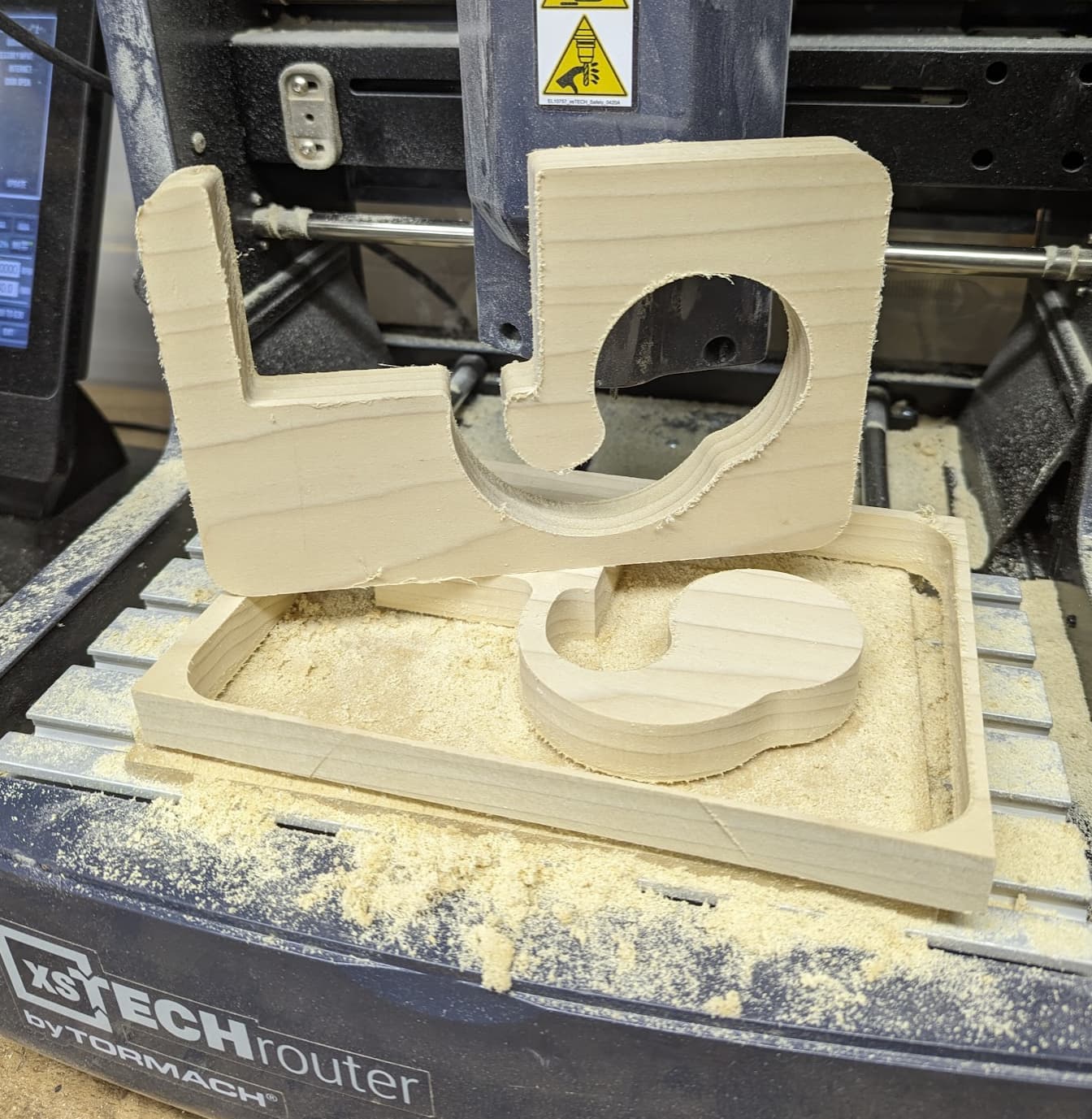
For this particular project, I chose to program from the center of the part. As the acoustic amplifier consists of three separate panels that are designed to fit together, working from the center ensures that they all share the same center point and should align together seamlessly during assembly.
The other reason that I chose this origin is that it allows me to visually illustrate how the WCS works in relation to the machine work envelope. As this project takes up a large portion of the machine work envelope, we are actually going to set up this project differently than most machining jobs and use the machine center of travel to determine stock placement in the machine.
As the machine is referenced at the extreme limit of travel, we are going to zero out our three axe
s at machine home for this first example in order to illustrate part location vs machine location and how they correlate.
To find the very center of the machine travel, we are first going to zero our three axes at their first extreme limit, which is machine home.
Reference the machine if you have not already, and then we will zero out all three axe
s at this location:
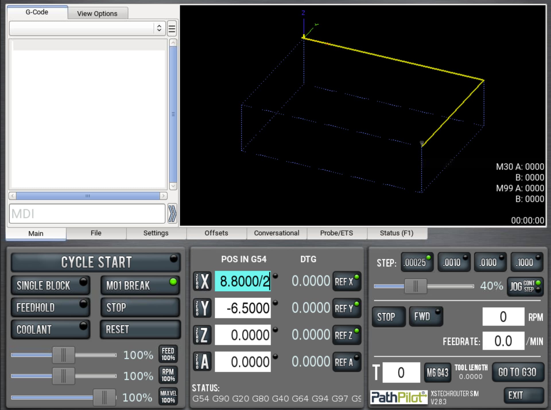
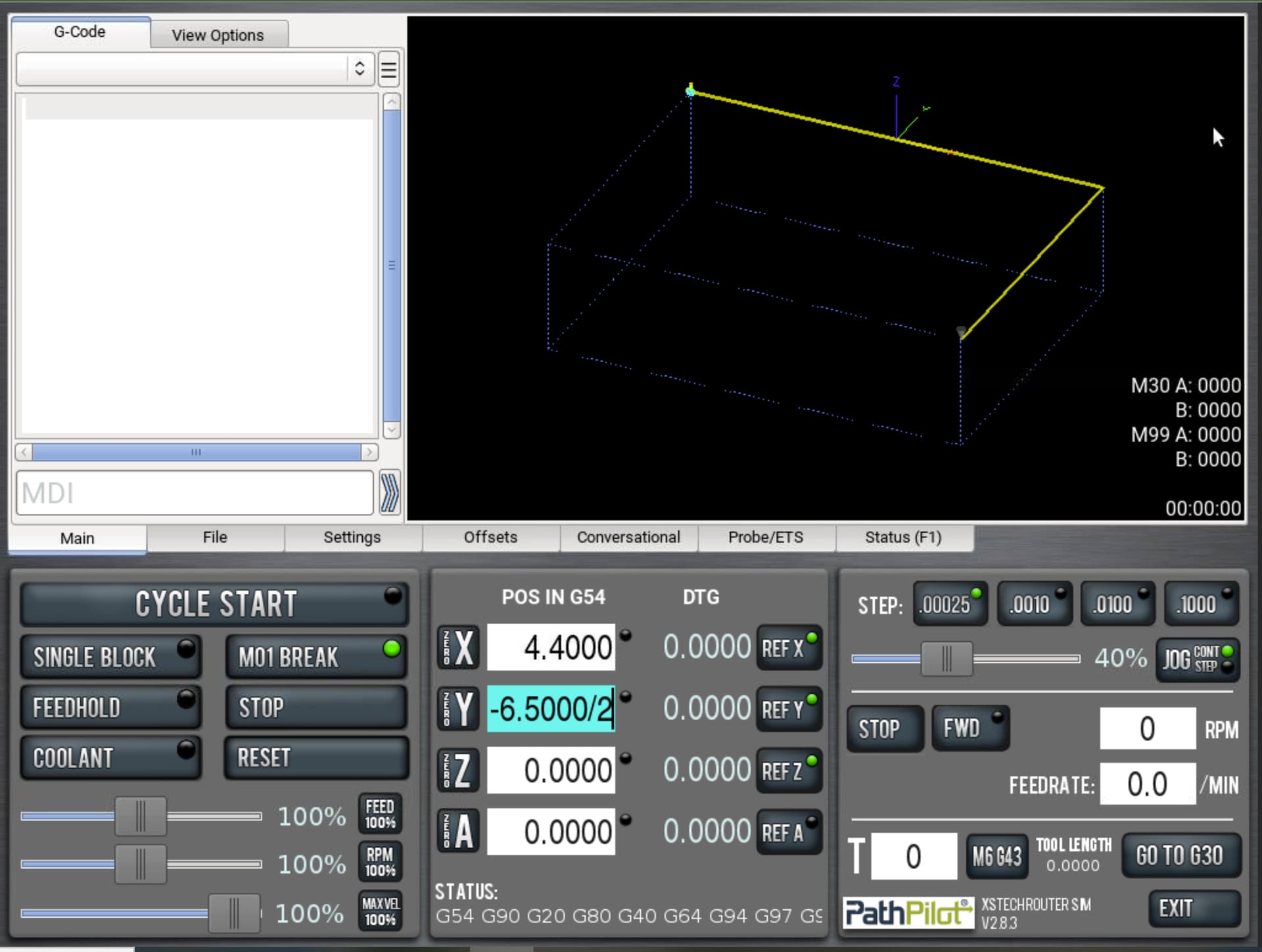
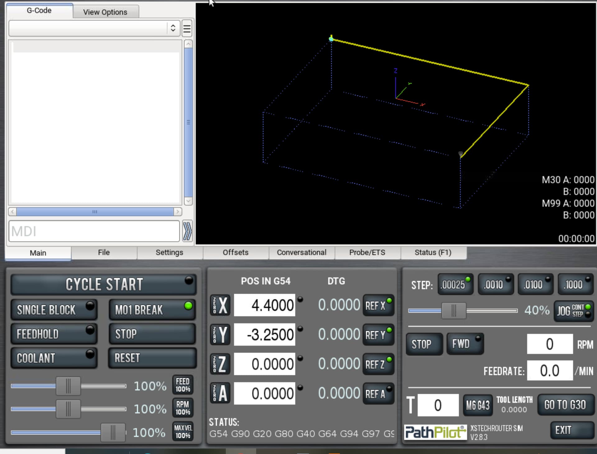
Starting with the X axis, jog the head away from the limit switch all the way to the right side of the table, slowing down when you approach close to 8.8 inches on the X digital readout (in the center panel below POS in G54). When the axis stops moving, you are where you need to be in X — at the other extreme limit. Using the incorporated calculation feature in PathPilot, you can simply add /2 at the end of the value and it will calculate Z as at half this distance — ergo — center of travel. Repeat the process for Y, moving the table back to about -6.5” and dividing by half.
You have just defined the origin of your current offset to be at the center of travel in X/Y. (Z is different, but we will get to this later in the project.)
Normally, the origin of the offset is based off a physical feature on the part stock — but this exercise is a bit more about tying together the physical location of the part position and how it relates to program locations.
As I based the program off of the center of the part, we will be lining up our workpiece to the tool, whereas typical setups dial the machine into the actual measured position of the part in its fixturing via indicator, probe or edge finder. We will eventually work our way into that in a later project.
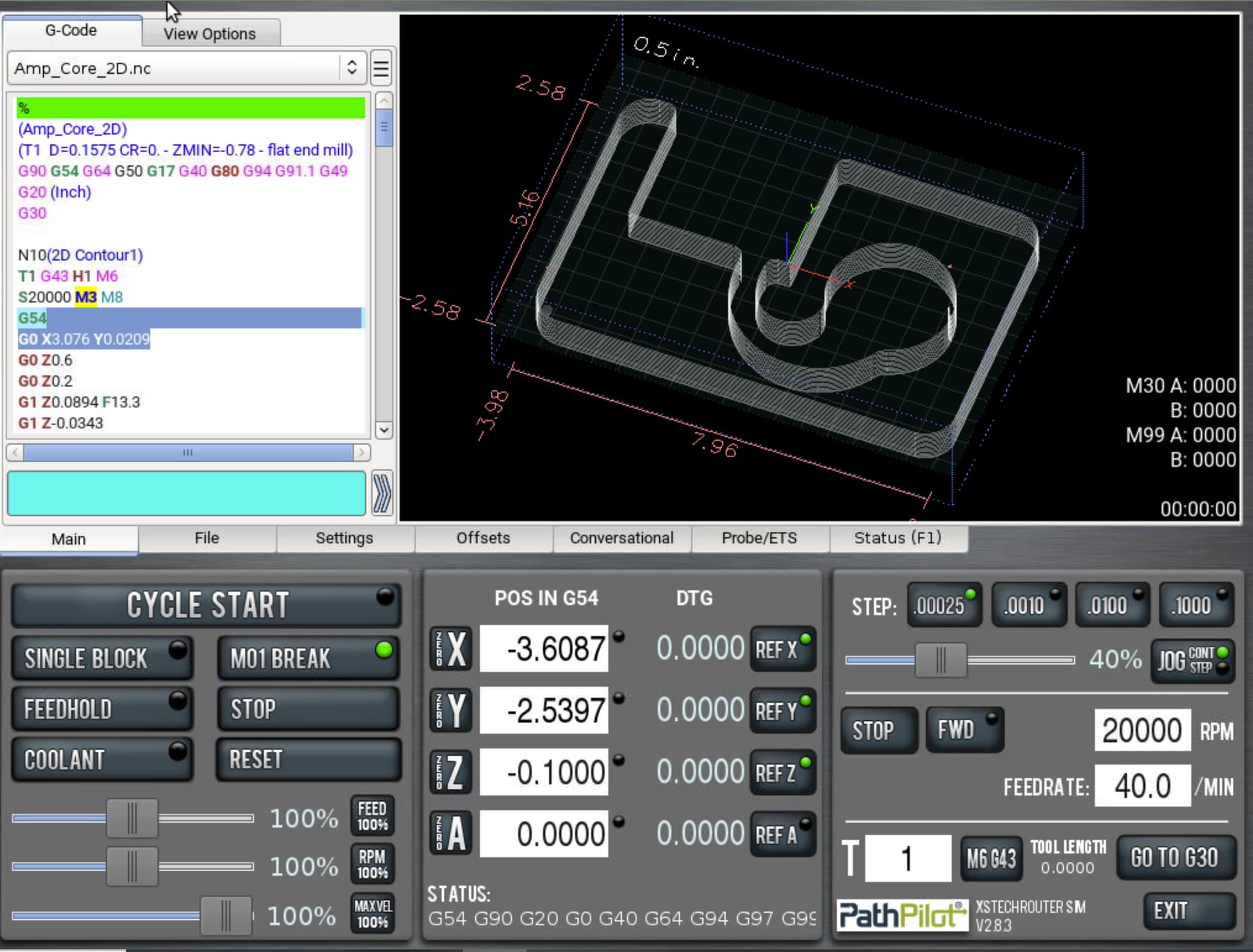
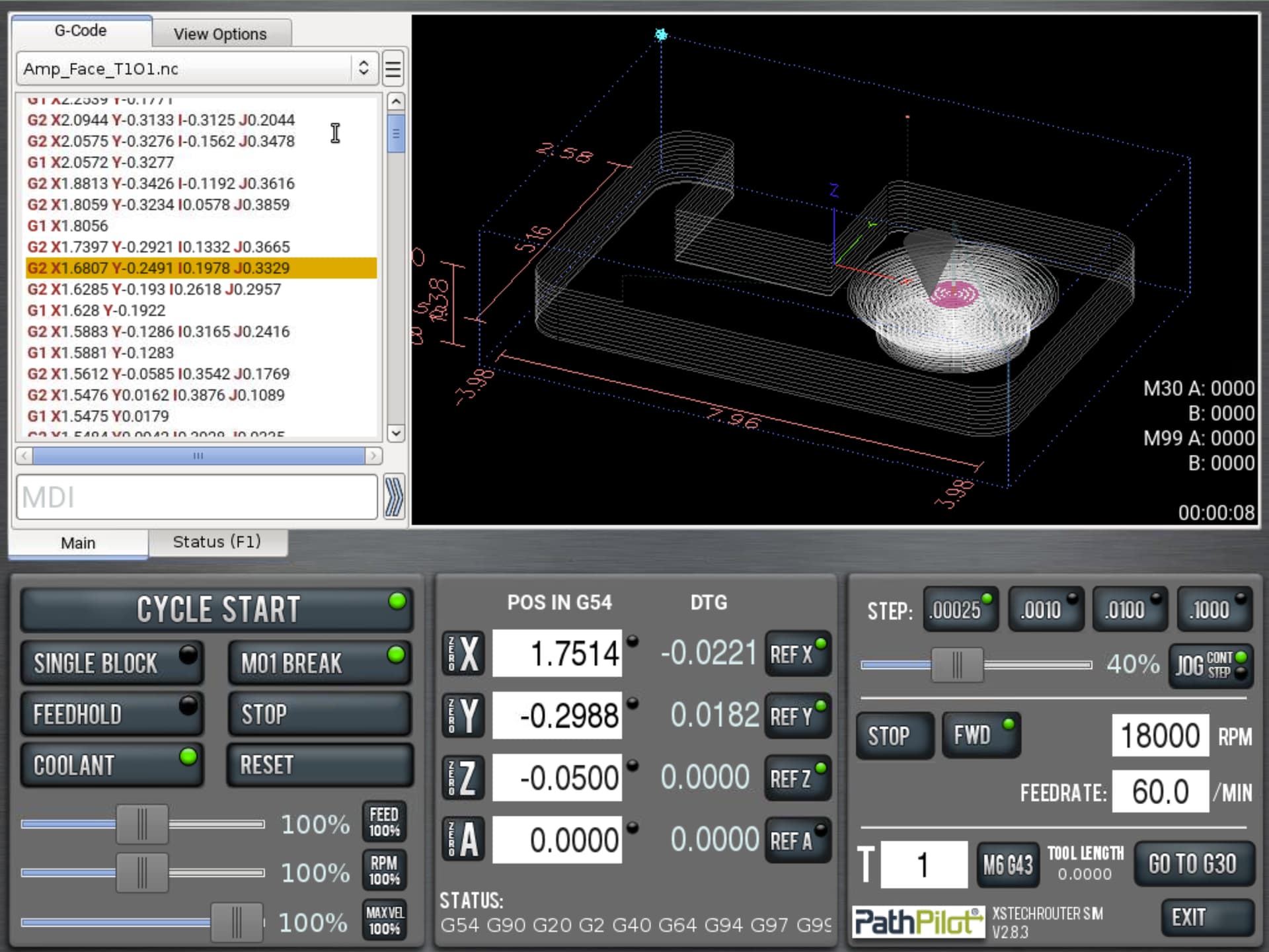
Your screen should have values close to the screen shot below. Note: If you are off a few ticks — it is not going to be an issue. This is not a high accuracy project, so we are not going to over complicate this and your part will still turn out just fine.
Lets take a trip to the center of travel. While you do not need to stress out over learning G-code in order to successfully run a CNC — there are a few handy commands worth knowing. I will describe each one as we use it — starting with one of the easiest one to learn.
To give your control simple one line commands to follow, you will utilize the little screen below the G-code dialogue box. This box is called the MDI line. It stands for Manual Data Input and basically it is a way to toggle certain settings in the control (like metric to imperial settings or single axis move commands.) You will not be entering full code here — just one line commands. It’s like asking a dog to perform a simple task — fetch, sit, turn on coolant, etc.
In this case, we are going to ask the mill to go quickly to the center of the table, which we just declared to be our X0Y0 location by splitting the overall travel by half. This is now a determined point that we can reference. The command will be G0X0Y0 — which broken down into common English means:
G0 (make a rapid or quick move to)
X0Y0 (Current offset position for X0 Y0)
The machine reads this as run to the X0Y0 position in current offset, which is G54 (offset label will always be the first G line on the bottom Status callout).
Click in MDI field until the cursor blinks, then simply type G0X0Y0 — then hit enter.
The table will move the head to the center of the physical router table in X and Y.

What is all this offset/G54 stuff and what does it mean?
When we set up the reference (home) positions at the beginning of this exercise — we were telling the stepper motors to sync up to a somewhat predictable location and send a signal to the control when it reaches its destination (the limit switch). The control records this position as an absolute master to where it will measure all of the additional coordinates from when it is mapping out the toolpath from your program.
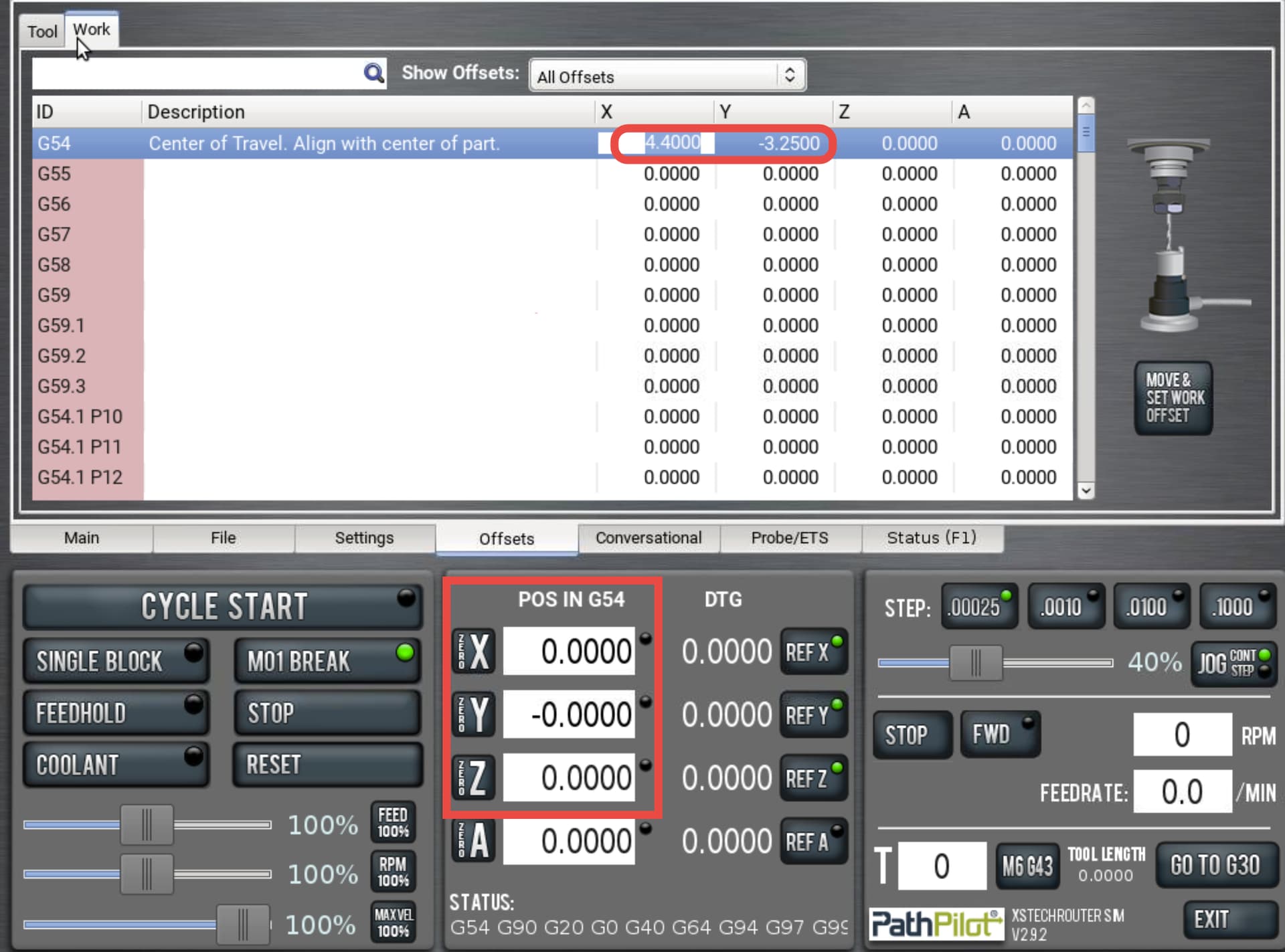
This location is used by the machine (known as a machine coordinate system). If you can recall when we were setting up the X0Y0 from the extreme edge of travel — the measurement at the extremes was at or near 8.8” in X and -6.5” in Y. Then we divided this number in the digital readout, which recorded the primary offset as zero for the operator facing coordinates. Note that the location of the G54 in the work offset table is the same value as if you were to count the graphical distance from the limit switches to the center of our workspace, which for this project, also happens to be where we are placing the part.
Multiple offsets come in handy for a for a magnitude of applications, but one of the most common uses is machining or programs — or part programs, in a single set up. This opens up the opportunity to run the machine unattended and maximize the production of each machine setup.
In this case, we are only dealing with a single offset — and the most used one — G54. PathPilot currently has a total of 500 storable offsets, meaning you can store up to 500 different work locations on the table.
At this point, we have not set up our Z origin yet, as this particular program is set with Z0 at the top of stock. We will need both the tool and the stock in the machine in order to set up the Z0 for this set up.
Let’s start with the tool as we will also be using it as a visual aid for lining up the stock.
There are a few things you will want to keep in mind for the tool setup.
• Always verify the final depth of the toolpath for the tool that you are setting up. This particular project is designed to be used on standard stock that is approximately .75” thick. The MDF will be serving as a sacrificial plate — which means that the program is designed to cut through the wood stock and into the MDF. We are going to be going about .03” beyond the nominal .75” depth, so you will want to make sure that your tool is hanging out of the nut at least .78” so that you do not collide with the top of your stock when you reach bottom depth.
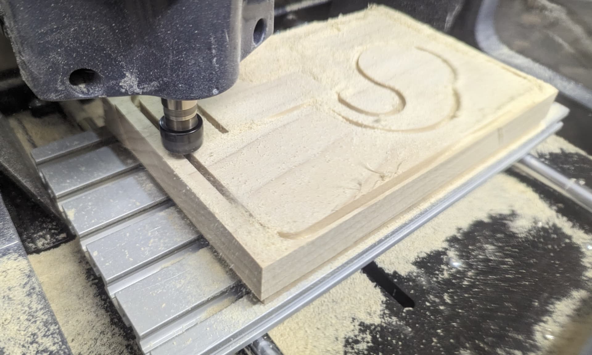
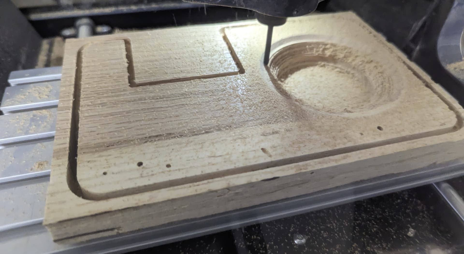
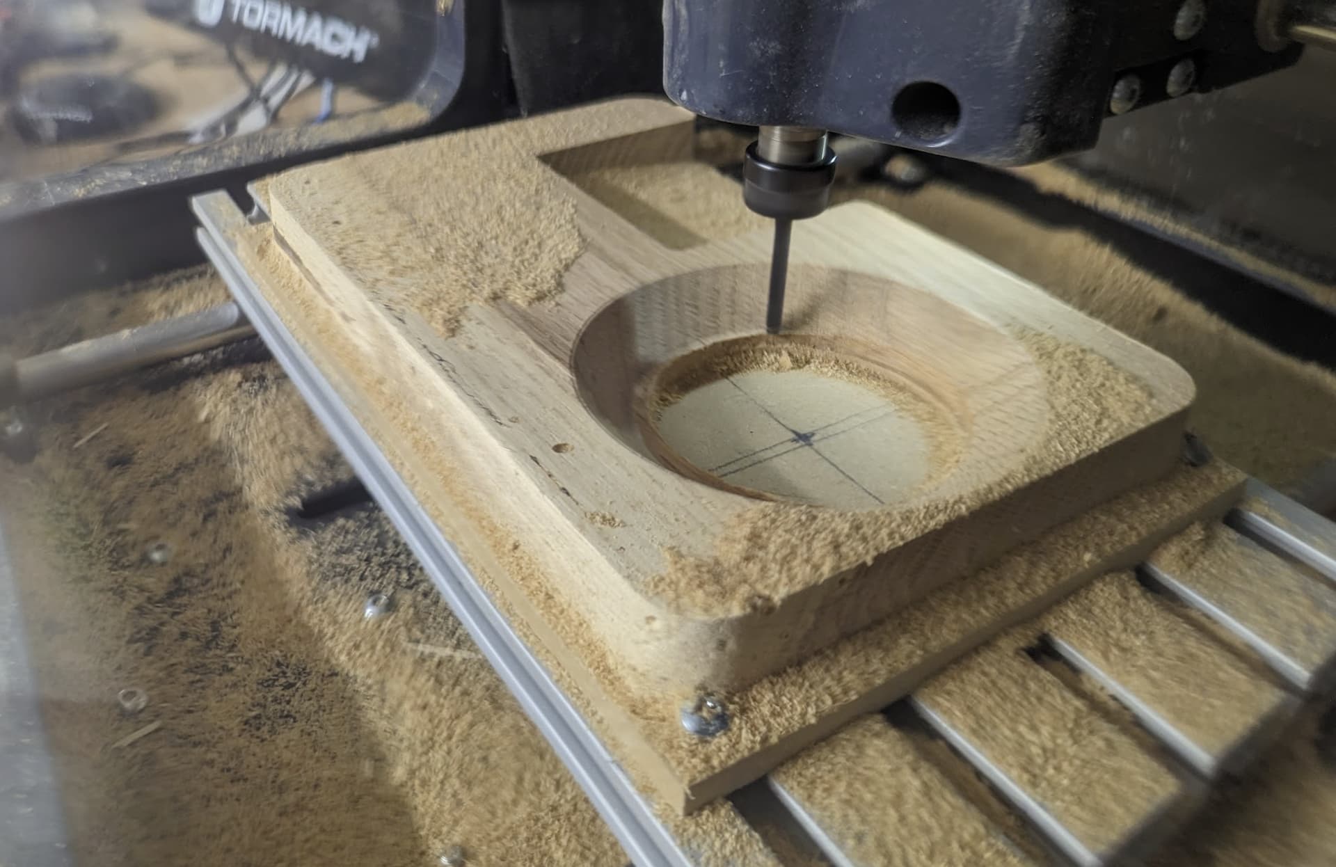
• This project will take two tools, with most of the material removal being done with a 4mm flat up-cut bit. (PN 39174). The final toolpath on the amp face will be a ball endmill as it is a 3D surface and the ball endmill will produce a smoother finish for this surface and will clean the stringy finish that you get from roughing out the sound hole with a flat endmill.
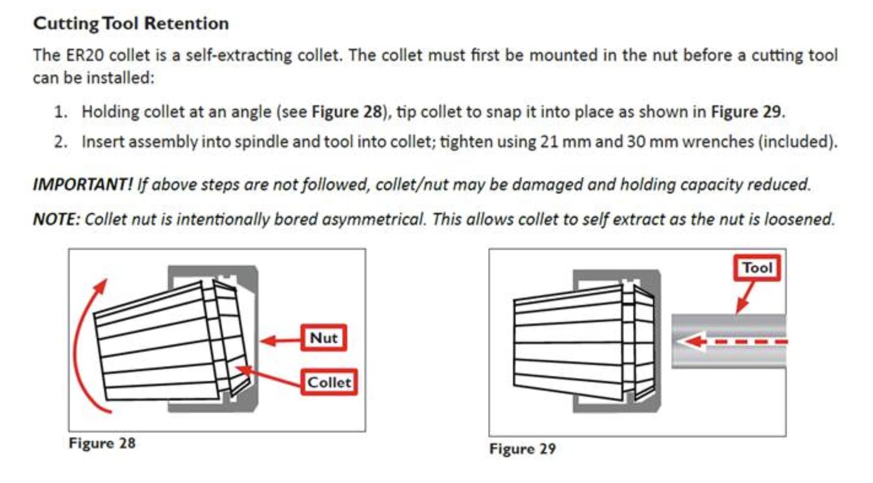
Remove the ER11 nut from the spindle and snap in the 4mm collet. The collet snaps into the nut at an angle so that the undercut fits into the retainer lip. Once the collet is snapped in and flush to the face of the nut, you can insert the tool into the collet and screw the nut back into the spindle.
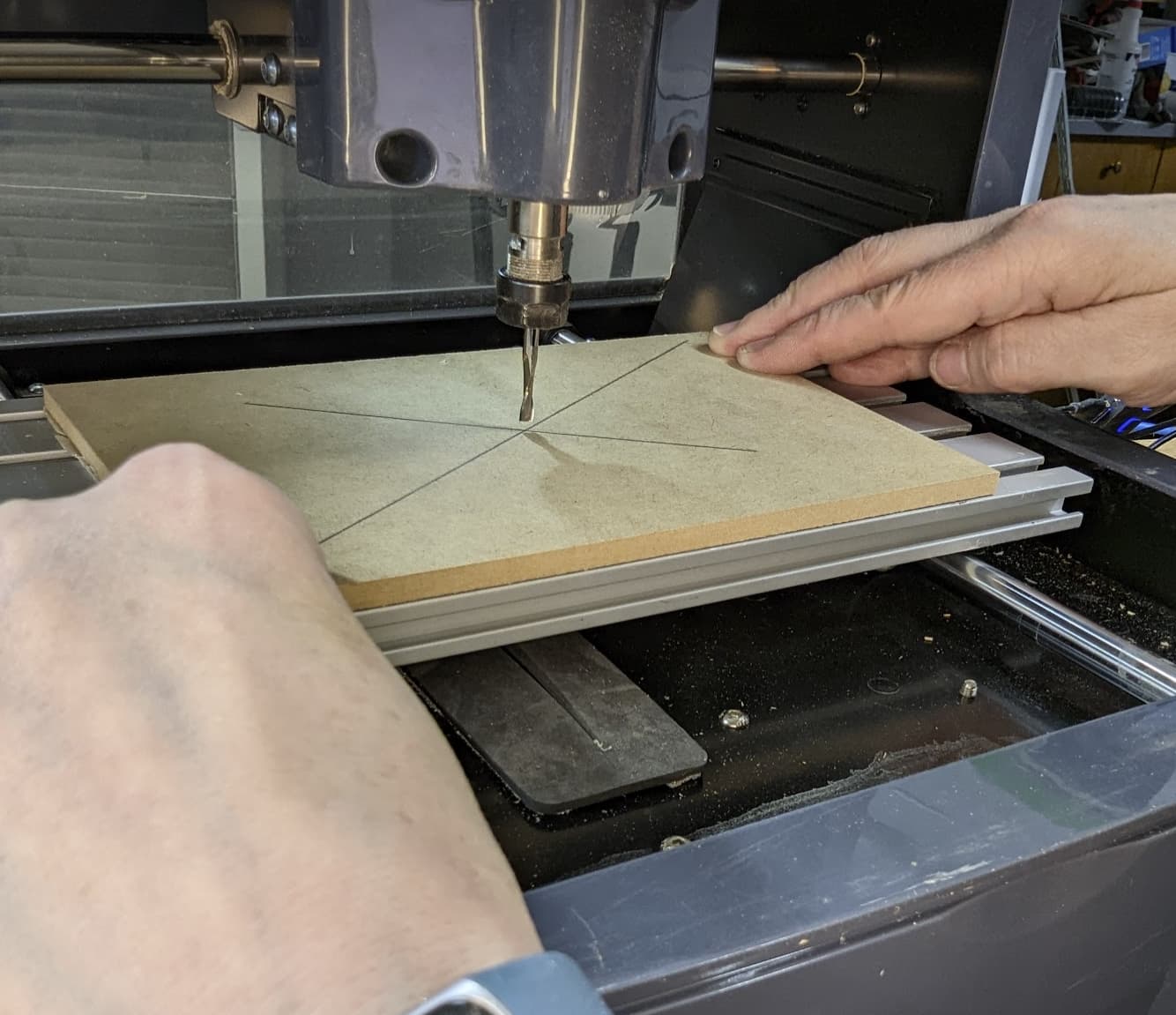
We will be using the MDF as a plate that we can cut into past the part depth, serving as a sacrificial plate and our extremely simple form of fixturing. We will be placing this plate in the center of the machine travel, where we will also be aligning our stock.
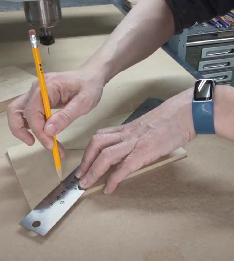
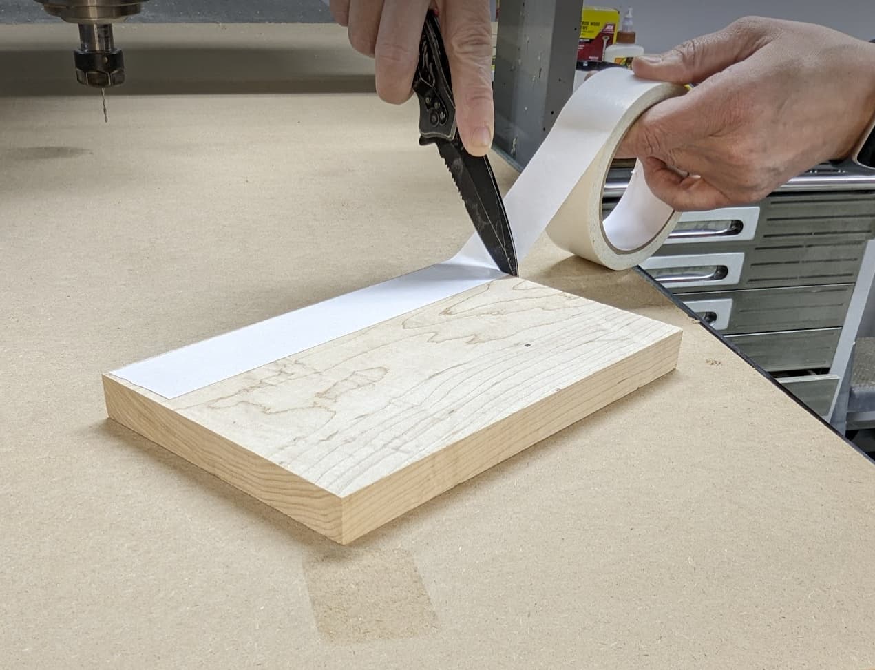
Using the straight edge, mark a line from corner to corner to mark the center of the plate.
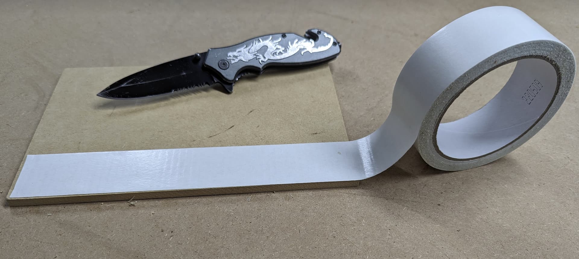
We will be using an extremely simple form of fixturing for this first project — double-sided carpet tape. I have tried a variety of tapes and have always had the most success and hold with Duck Indoor/Outdoor Carpet Tape.
https://www.amazon.com/Duck-392907-Indoor-Outdoor-1-41-Inch/dp/B000BO4QZ0?ref_=ast_sto_dp&th=1
There are a few caveats with this fixturing strategies, and they should be noted.
• Carpet tape and other adhesive fixturing methods — while simple and effective, has limits that should be considered during set up and programming.
o The table and the medium being taped should be clean and clear of chips, dust, burrs and oils.
o Porous, oily or material that is bowed or not flat can reduce the adhesion and increase the risk that the part may move during the machining process. Other fixturing methods or material prep (planing, cleaning, ect) may be required for secure fixturing.
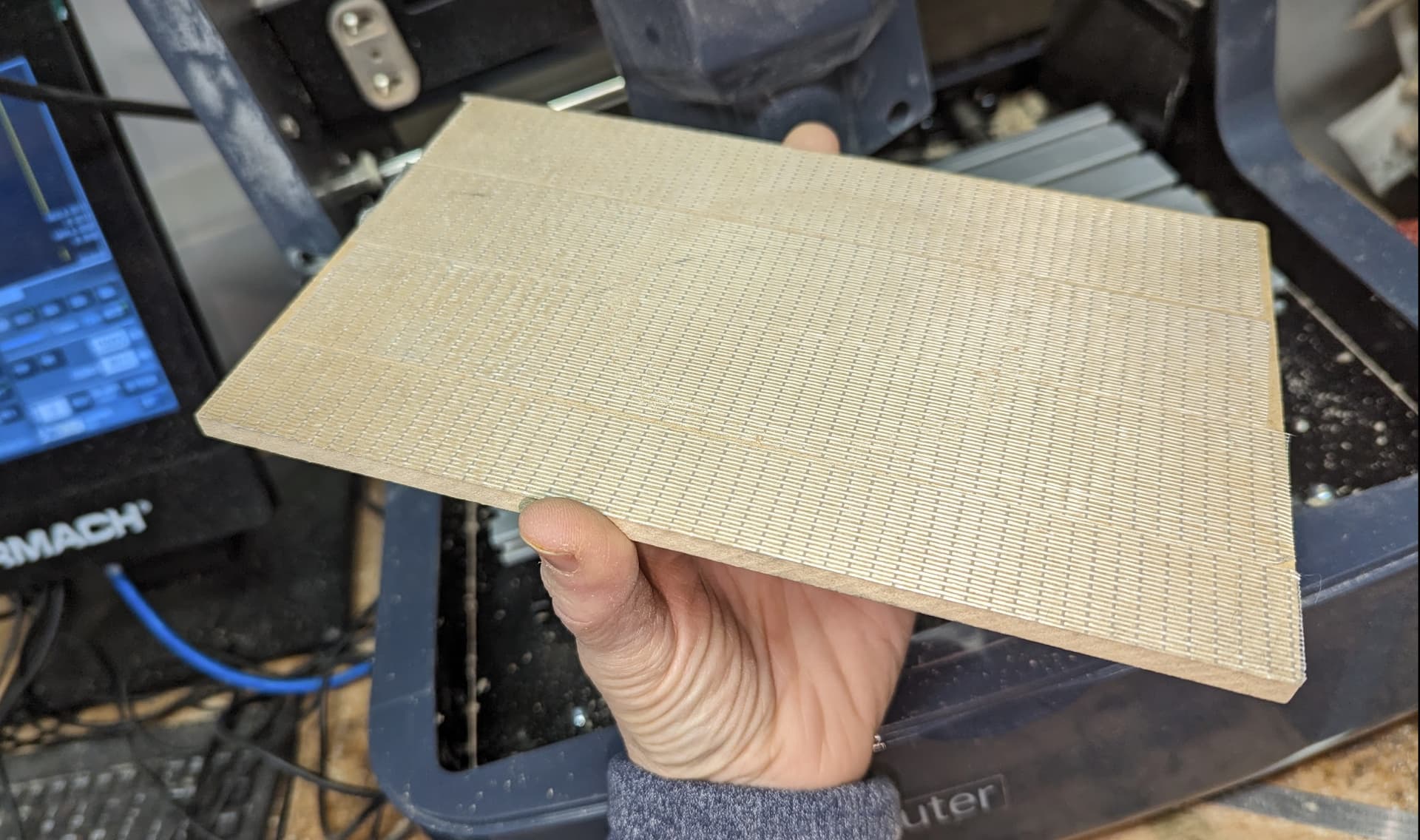
o The MDF board should be replaced as a fixture once it starts becoming ‘fuzzy’ from use. The tape works best on a smooth and firm surface.
o Chips and sawdust that build up in the T-Slot channels can build up on the tape and reduce the adhesion.
o Aggressive lateral cuts (in X/Y) as well as fast change-of-direction tool moves are not ideal for a simple adhesive setup as they can fatigue and loosen up the tape’s hold.
o A good adhesive can be amazing for holding parts. The same characteristics that make this method effective can also be an exercise of our patience when trying to remove the tape from the table. A few tips:
Have a thin but firm scraper handy to get the edge of the plate up. A small pry bar can also be used, but be mindful of scratching or denting the extruded aluminum bed. Also, be extremely careful to pry gently to reduce slipping and injury to yourself or the machine.
The tool should be removed when the plate is being removed to reduce risk of injury
If the tape has a stubborn hold on your MDF/Table — focus on just getting a little clearance lifted in the corner. With a small dropper or brush, apply a little bit of mineral spirits (or WD40) to the underside of the loose corner. This should help to break down the adhesive and aid in the removal.
The tape and MDF should not remain on the bed for extended periods of time or during storage. As the tape ages, it can be more difficult to remove.
Pushing hard on the table in the Y direction can cause the table to move. If there is table movement during the removal process, you will want to reference the machine again if this occurs. Moving the spindle head (Z axis) all of the way up with the tool removed and the table all of the way forward is the safest way to prevent injury during this process.
Flip the MDF and laydown strips of carpet tape closely and evenly across the back of the plate.
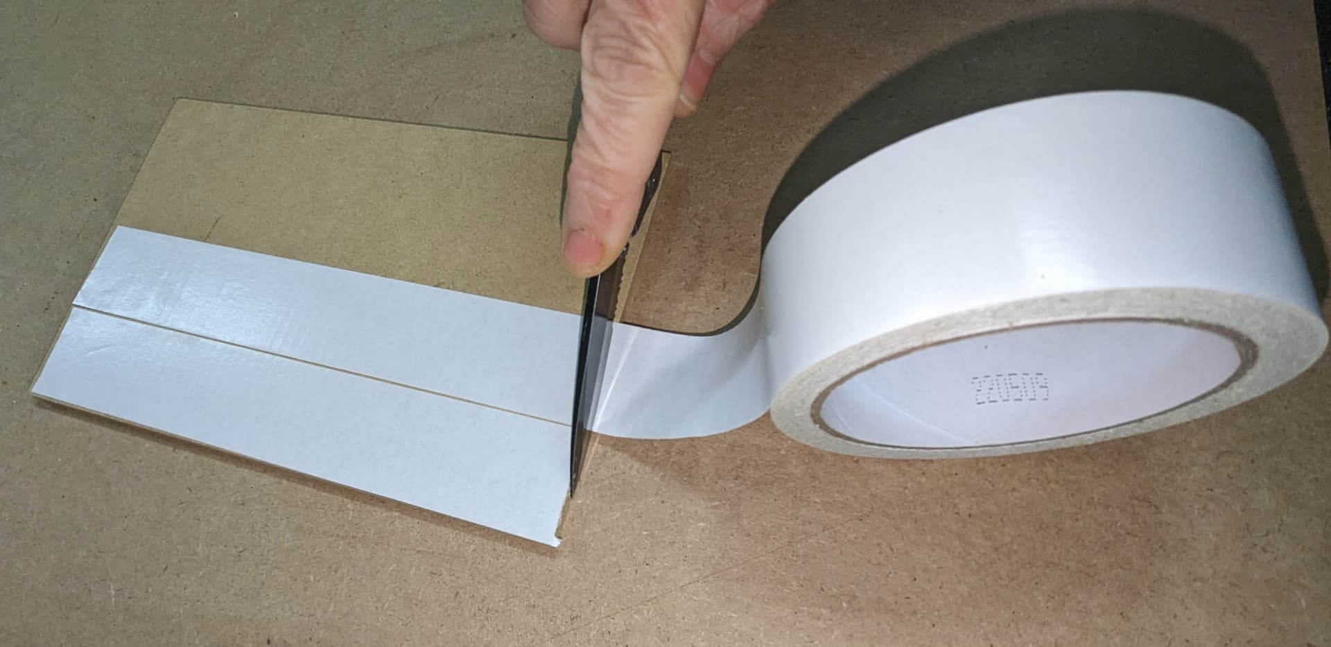
Note: You will be repeating this process with your stock material as soon as the plate is positioned and secured in the machine.
Once the tape is applied to the MDF, remove the backing and position the plate to the bed with the center aligned with the tooling with X/Y axis in 0,0 position. (Move spindle head down to verify the center position, then up and out of the way once confirmed.) Firmly press the plate to the bed.
Repeat the taping process to the part stock. Then adhere the stock, on center, to your MDF plate. Firmly press and then give the material a gentle push and pull to ensure that the hold is secure.


We have one final axis to register before we can start cutting — the Z axis. The Z axis measurement is obtained by touching off the tool to the Z0 point on our part program, which will be the top of stock. This registers both the tool length and the distance from the Z axis home and the tip of the tool. There is a lot more theory and involved with this for more complex programs, but in this case, we will be just focusing on single touch set ups.
First, enter the tool number for the tool that we will be touching off for the first program — in this case, the tool number is one.
Click on the Tool field, type 1 and hit enter to register.

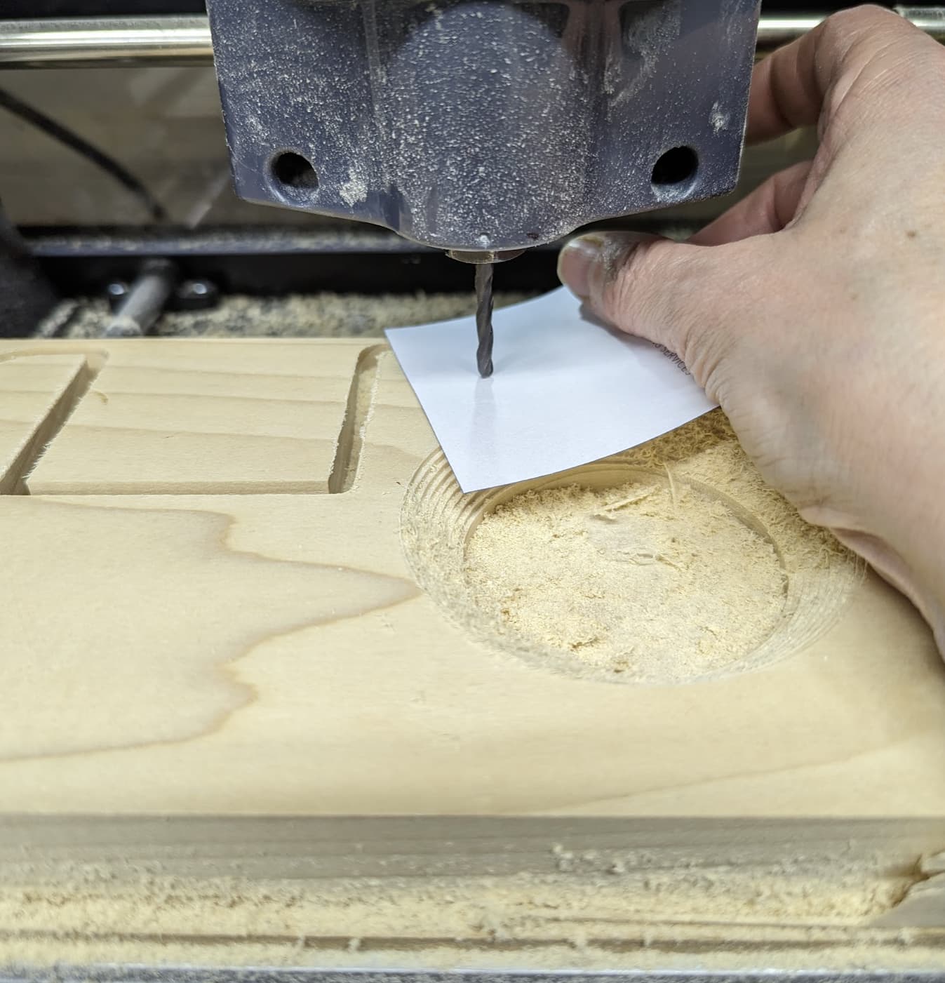
Slowly, bring the Z axis down toward the top surface of the part. Use a small slip of standard notebook paper or post it note to touch off the tool. Bring the Z axis down slowly while wiggling the paper between the stock and tool until you feel the tool grab the paper. Once there is a bit of drag, enter .003” in the Z column and hit enter.
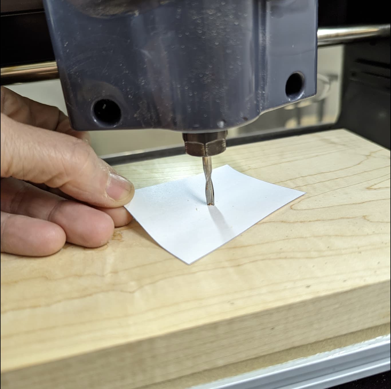
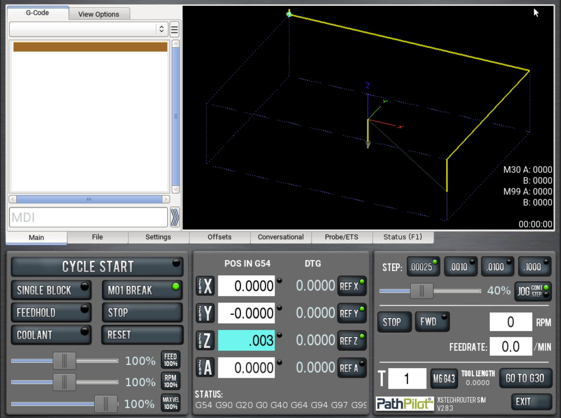
• The .003” represents the thickness of the paper. The reason that we enter this into the control is that it tells the control that the tool is .003 above the top surface without having to run the tool into the top of the part — risking breakage of the tool or blemish to your stock.
Now that we have the router set up, lets bring in our programs so that we can start machining.
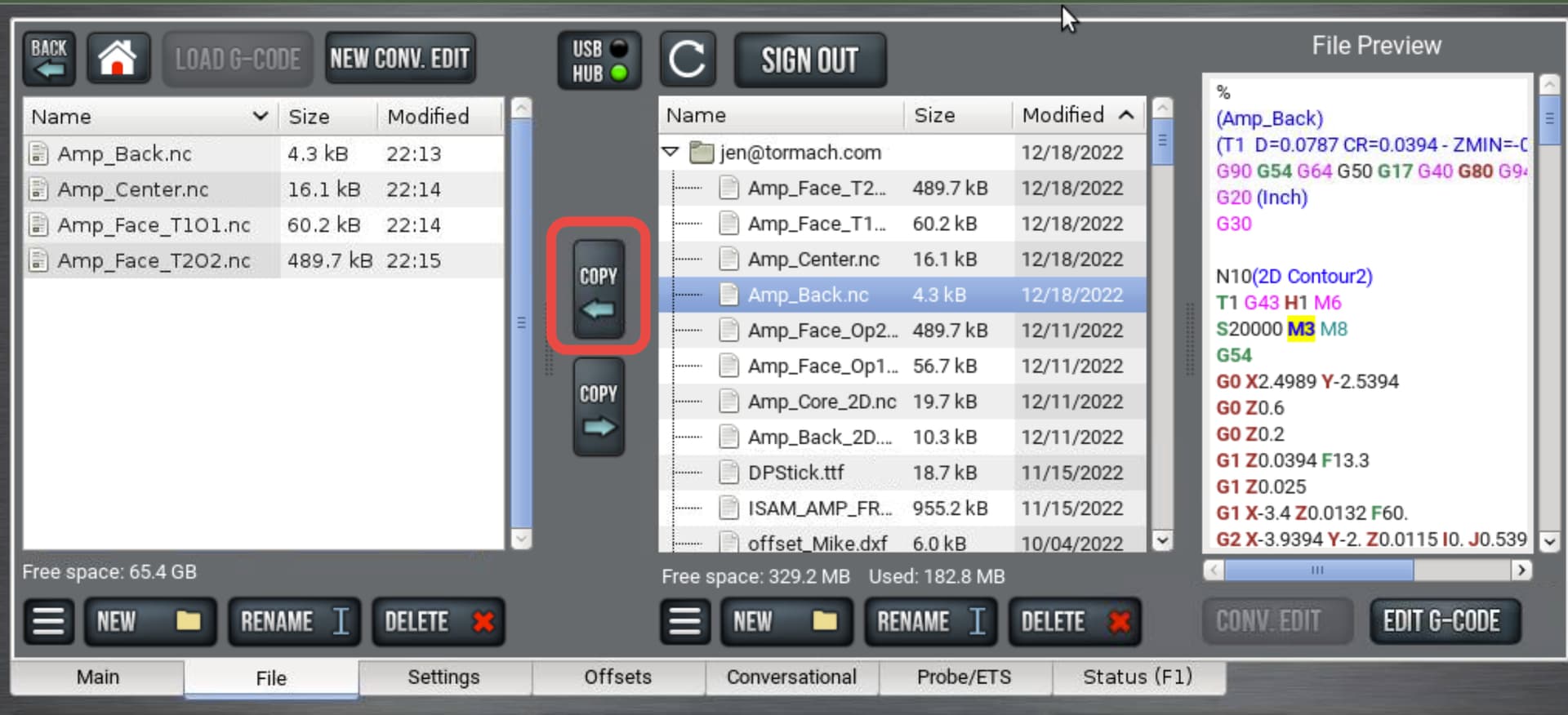
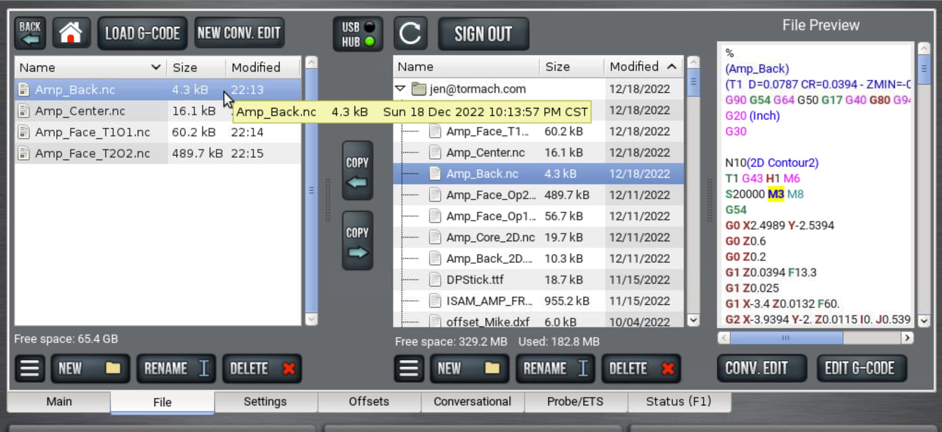
Select the programs that you will be running and transfer them to your PathPilot drive by highlighting the program name and clicking copy. The four programs that we will be using are designed to be run IN THIS ORDER:
1. Amp_Back
2. Amp_Center
3. Amp_Face_T1O1
4. Amp_Face_T2O2 (This final program will require a tool change)
Double Click on the program that you would like to load and run.
This will bring you to the main screen with a graphical representation of your part program in the work envelope/graphic screen. If you right click on the graphics screen, you will be given a popup menu. The menu will allow you to toggle to different view perspectives for quick analysis of tool paths.
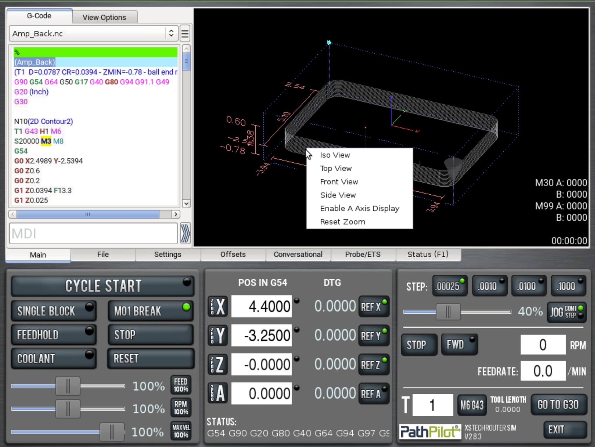
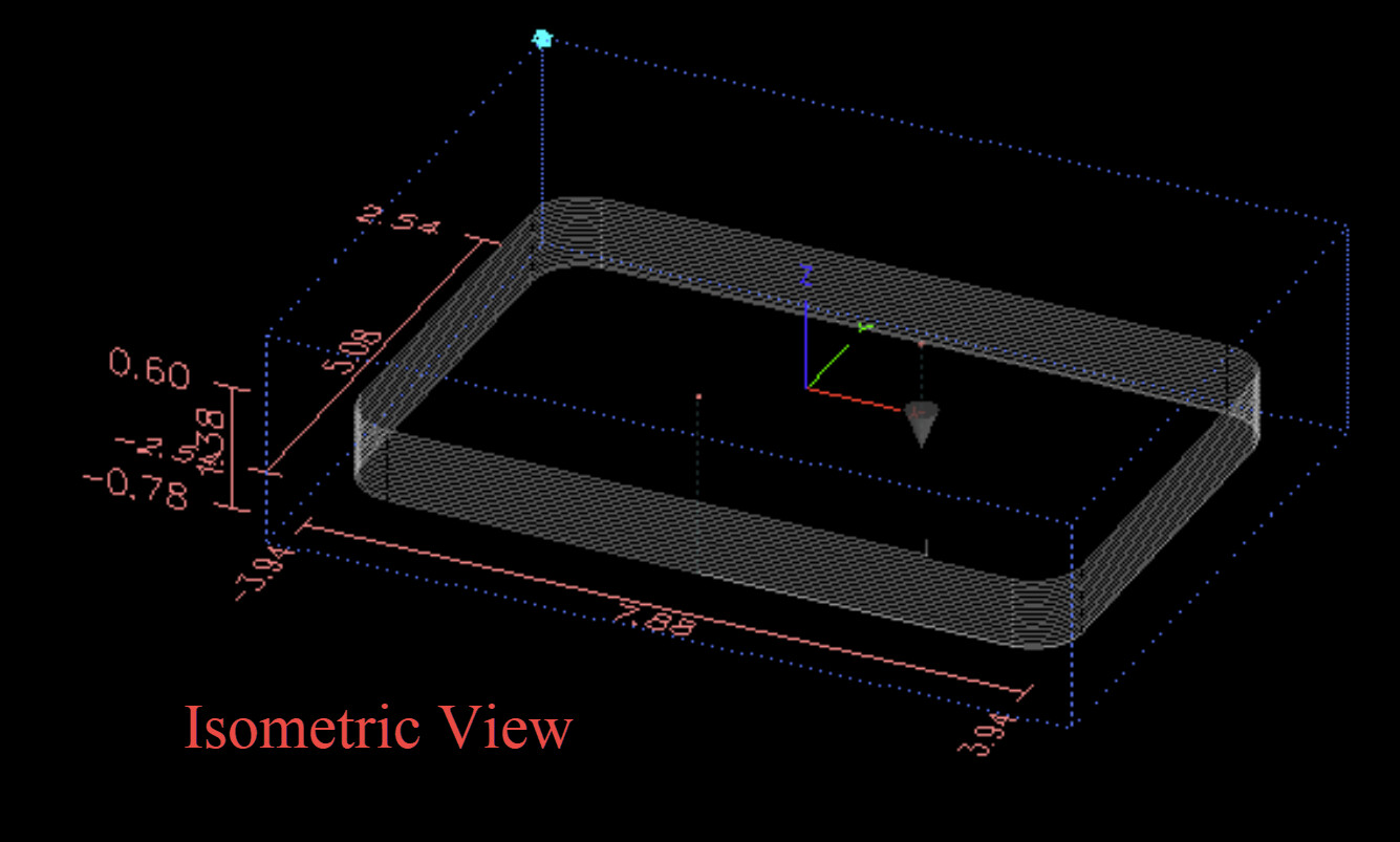
The isometric view gives you the best overall glimpse into the toolpath.
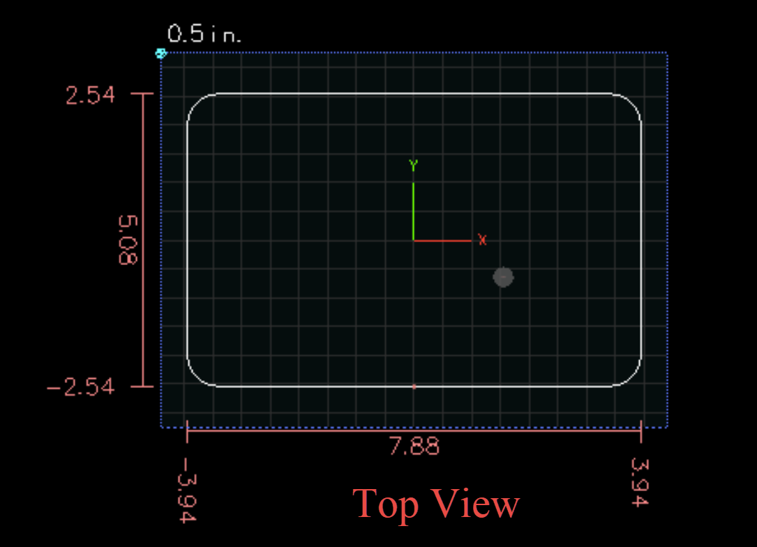
The top view allows you to view the overall profile of your part, as well as it’s positioning within the work envelope.
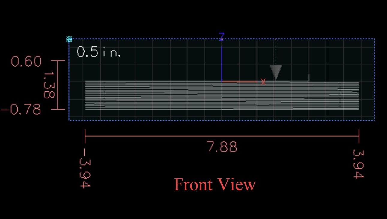
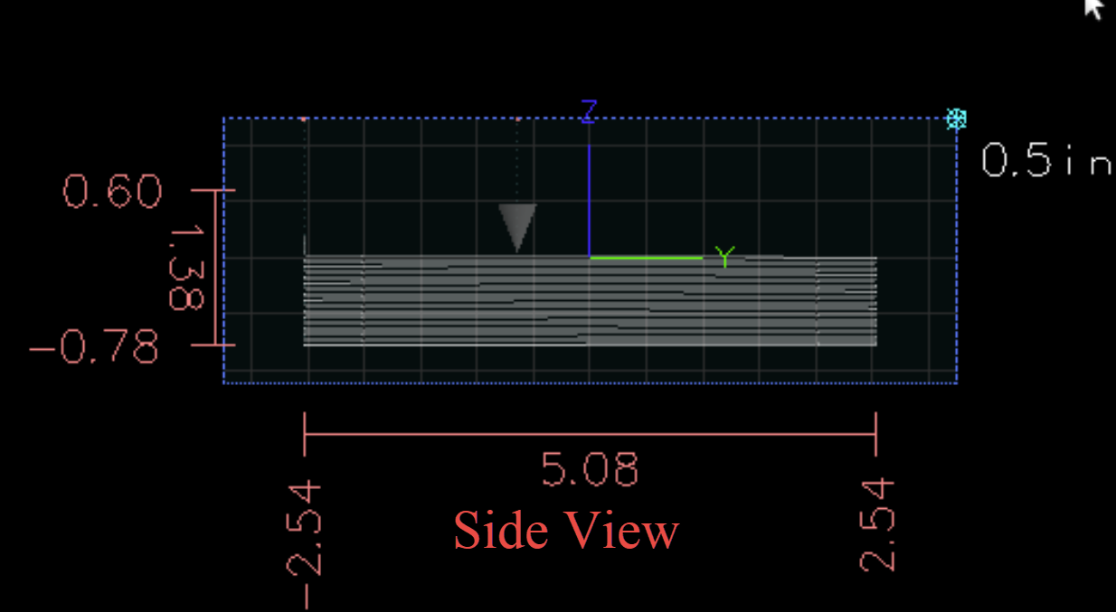
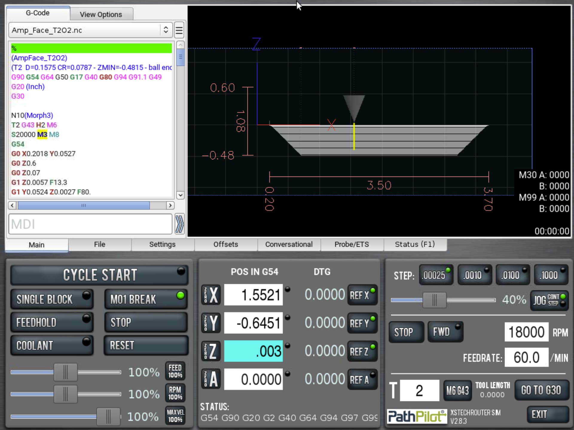
The front and side view gives a clear glimpse into the clearance height and cut depths for the tool path.
Once everything has been verified, you are ready to start the program.
1. Press Cycle Start.
2. Turn down the feed slider (controls cut rate)
3. Turn down the Max Velocity slider (controls rapid moves)
4. Keep an eye on your distance to go in Z, slowly rolling the max velocity rate and the feed rate sliders up until you are comfortable and the machine sounds as though it is cutting smoothly through your part.

It is advisable to keep an eye or ear on the part while it is cutting. This program will cut around the part, but the final few depth passes can break loose the skeleton or leftover material from the stock. It is always a good idea to be within spacebar range, as the spacebar will pause motion in the program if you experience chatter from a loose chunk of left over skeleton.
As material builds up in the kerf (path created by tool) and machine, you may want to pause momentarily to brush or vacuum out the wood dust. Build up of excess material can require greater tool pressure and can also cause your part to shift during the machining process.
Note: The depth of cut and feed rates in this program are designed to be a bit more conservative than would typically be required in order to allow for a variety of materials (hard woods, pine, MDF) to use the same program. If you are running the program and would like to speed up the over rides, you are welcome to make adjustments to the slider. Please do keep in mind though, that we are fixturing this first part with carpet tape, so more aggressive cuts can increase the chance that the part could move during the program run. You may experience some squawking of the tool due to deflection from the longer tool length in some materials. Making manual adjustments to the over rides by ear should help to tune out some of the harmonics.

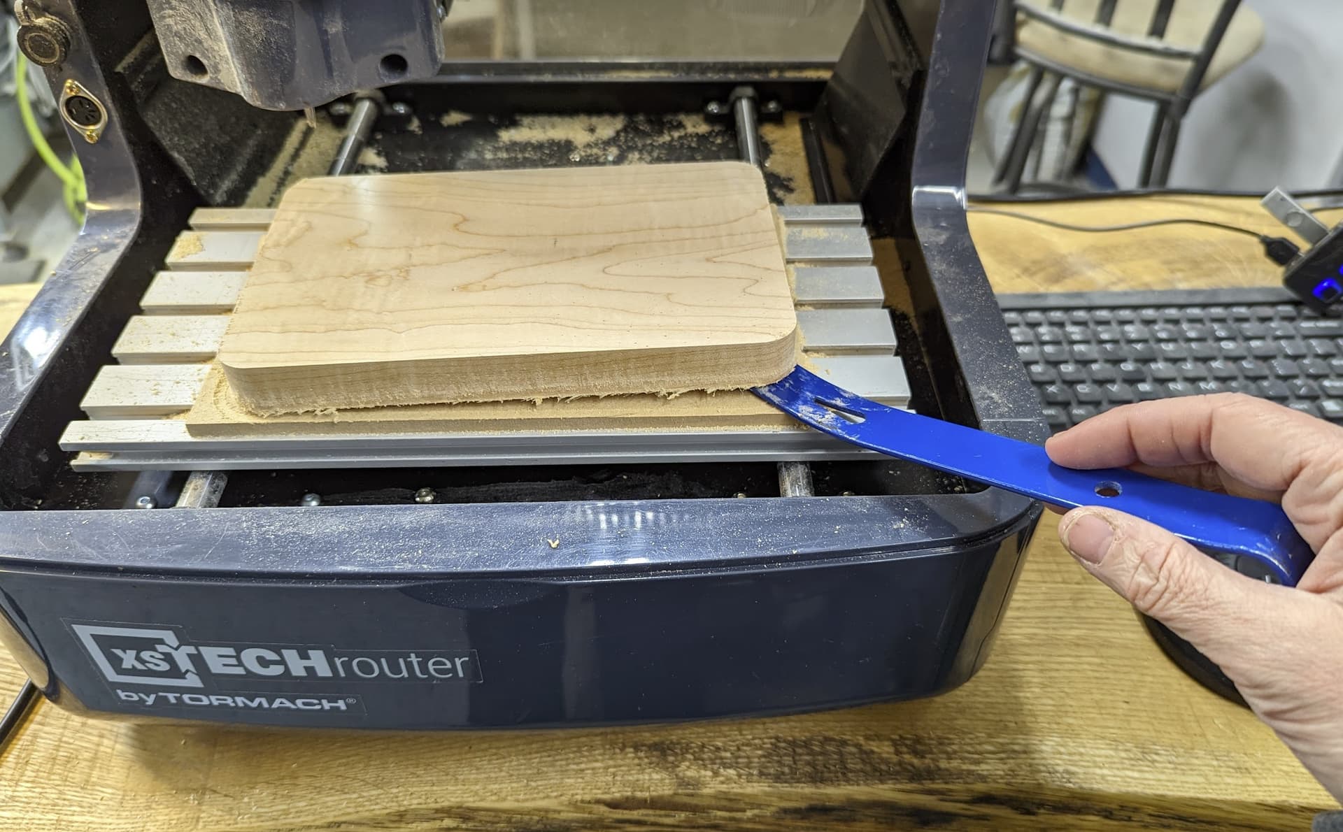
Once you part has completed it’s program, remove the skeleton and part from the mill. You may need to use a small pry bar or stiff scraper blade to gently remove the part and tape from the MDF board.

The set up for Amp_Back, Amp_Center, and Amp_Face_T1O1 will run the same 4MM flat up cut endmill. The set up process for all three programs will be the same as the set up process outlined above.
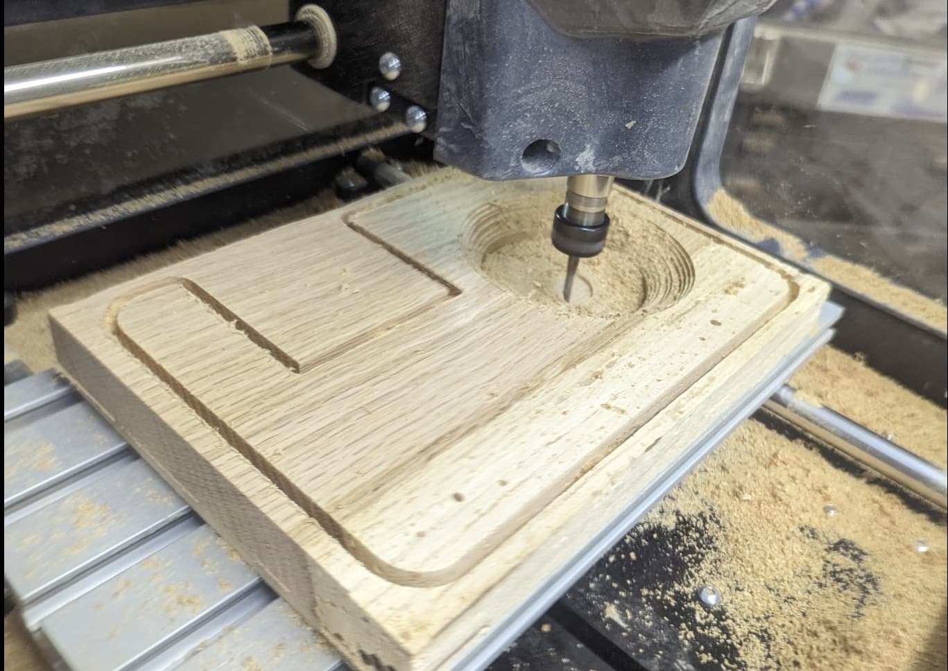
Set Up Tool 2 — 4MM Ball End Mill for Amp_Face_T2O2
Once you complete running the first operation on the amp face program (Amp_Face_T1O1), you will want to carefully brush/vacuum out the chips without moving the part on the table.
We will be changing to our second and final tool for this project.
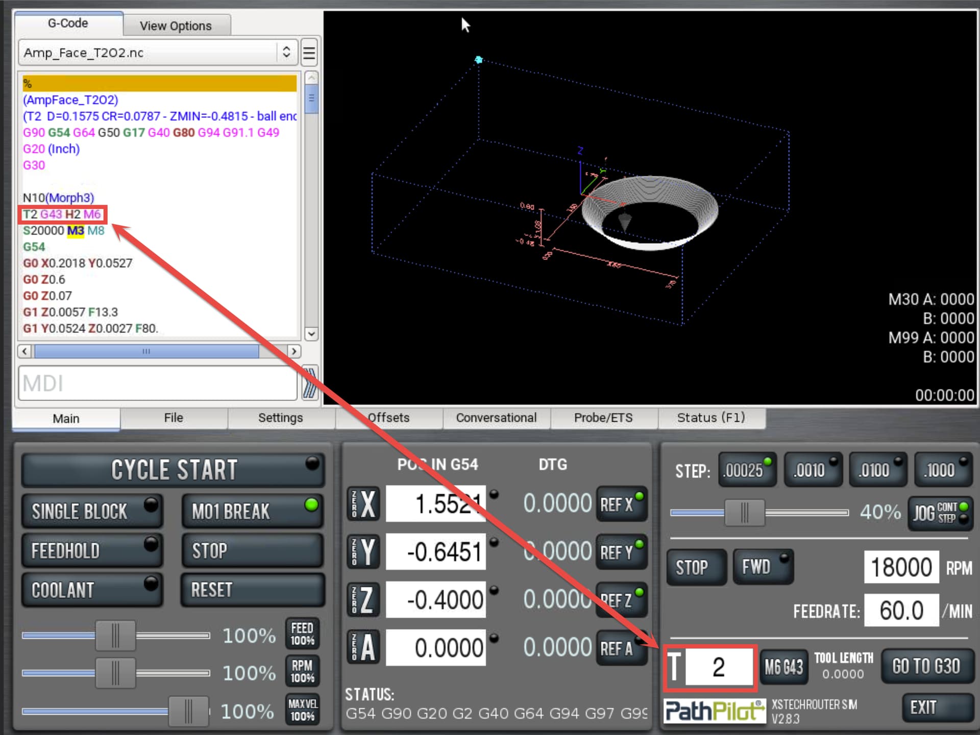
Load Program Amp_Face_T2O2
Note that that the first major callout is for T2. The G43 line will tell you which tool you will be running and the T number designates which tool is used in the program. In this case, we are using tool 2. Click in the T field, type the number 2 then hit enter to register.
Move table to the front of the router so that you have room to perform a tool change without interference from the material.

Using your two xsTECH spindle wrenches, loosen and remove the ER11 nut.
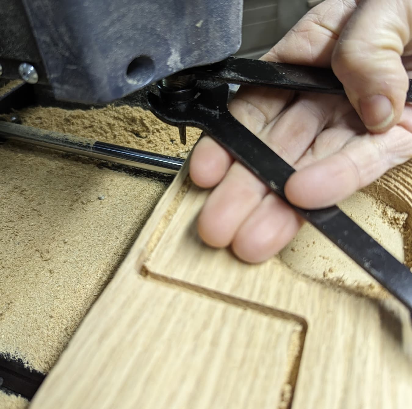
Remove the 4MM flat up-cut end mill and replace with the 4MM ball end mill.

Touch off the new ball endmill (T2) to the top surface of your part, making sure that T2 is entered in the main screen T field. If you are using a slip of standard paper for touch off, add .003 into the Z axis read out and hit enter when the paper starts to drag. Note: You will not need to change X or Y as only the tool length position is changing (Z axis).
Once the tool is set up, you may hit cycle start and run the surfacing program for the amplifier. (Amp_Face_T2O2).
Once all three parts are run, sand and file as needed.
You may choose to personalize the components of your amplifier before assembly. If you will be using the xsTECH for the customization, I will be covering this in a future project walkthrough. You may also use a laser engraver, wood burning kit, Dremel or other rotary tool, hand router, etc.
Once your amplifier components are prepared with your preferred finish, it is time to align and glue up the assembly.
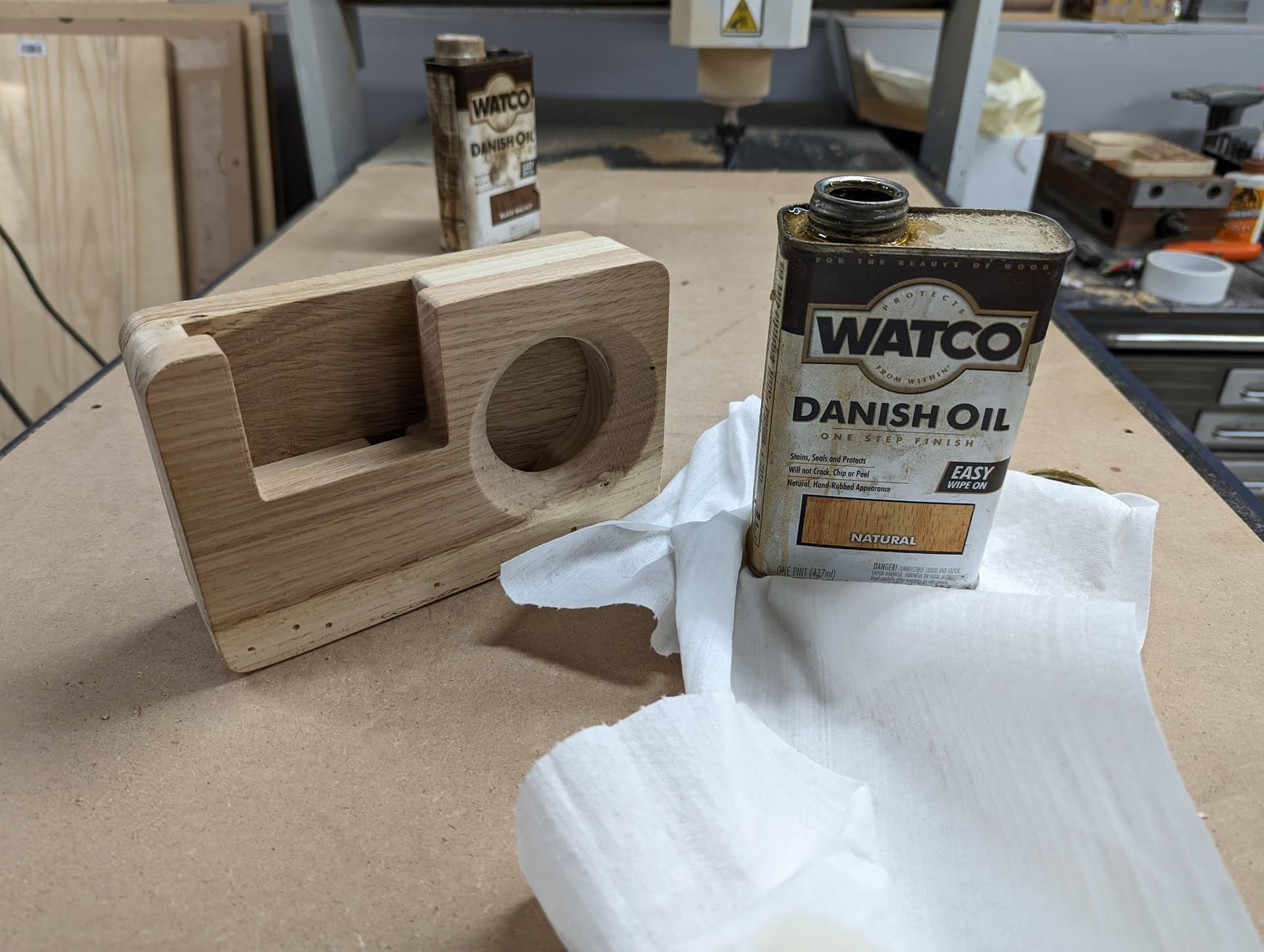
NOTE: If you are using an oil based stain or finish, try to minimize the amount of oil that contacts the gluing surfaces. Or if you are using a water based stain, wait until your components are completely dry before assembling to ensure proper cohesion of the panels. Personally, I use Danish Oil, but choose to do this as a final step, as I typically will sand the amplifier one final time when it is assembled to ensure a smooth blend between panels.
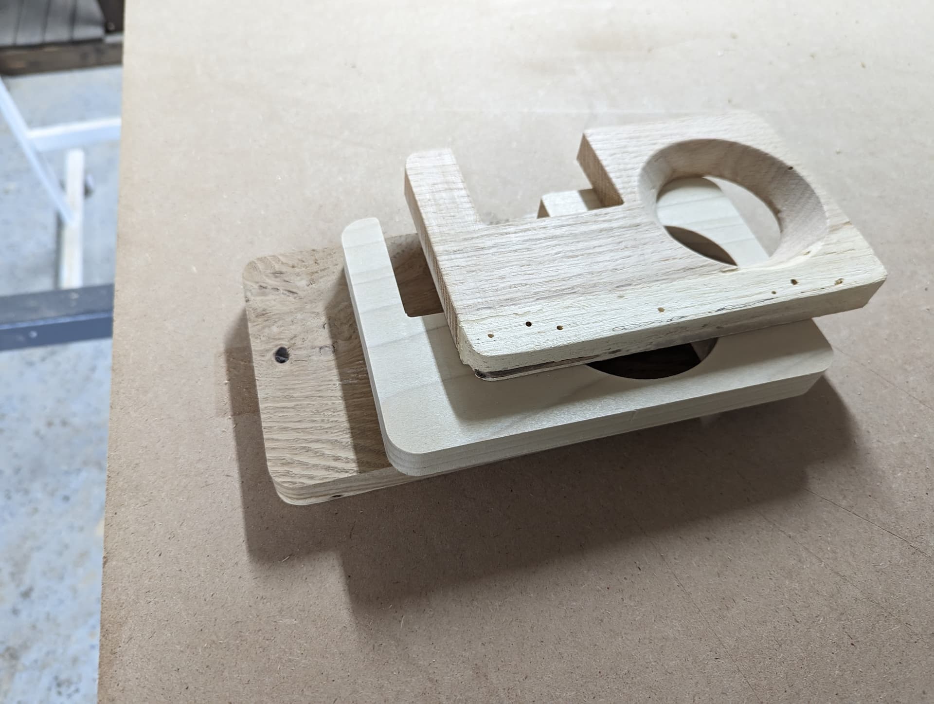
Note the surfaces to be glued and how the panels line up. As the programs shared the same center, your panels should line up extremely well.
Apply a thin layer wood glue to the surfaces that require glue. I prefer to use a brush to spread on the thin layer to ensure coverage but to also spread out any excess glue so it does not seep through the sides of the panel.
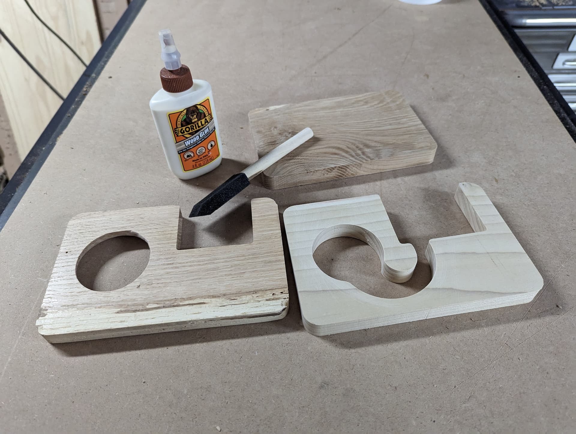

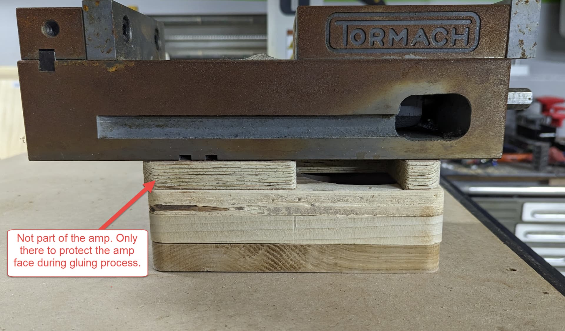
To set the assembly, you may use a wood clamp. Or, if you do not have a proper wood clamp, you could lay something heavy and solid on your assembly to ensure that the glue sets the panels firmly. (I used an old rusty vise that I will be reviving in the future. I added an old sacrificial test panel to the top layer (without glue), as a buffer, make sure that the rust did not contaminate my amp surface. (Your finished amp will only be three panels.)
Finish your amplifier by sanding/staining/oiling/burning, ect.
Find favorite playlist and turn up the volume. Insert phone. ROCK ON.