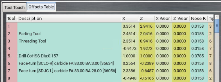
I have had my 8L for about a year now and am finally getting into gang tooling. In doing so, I have questions about the Tool Table data due to some odd things happening while working on the negative side of the workpiece. In the 8L, the table consists of two parts. The first contains tools number between 1 and 99 and contain entries for the tool description, X and Z wear offsets, the tip radius, the front and back tool angle and the tool orientation (1 – 9). The second half of the Table contains entries between 10001 and 10099 and contains the X and Z zero offsets in G53 units. My question is what are the values in this second half of the table in the Front Angle column?
Thanks for the question! I want to clear up some confusion:
The lathe tool table (both 8L and 15L) stores geometry offsets and wear offsets. The “X” and “Z” columns are the geometry offsets, which are applied when the tool is changed via the T command, either via MDI or from running a line of G code. Either geometry, wear, or most often both are applied with the T command (unlike the mill’s g-code command which requires G43 to apply offsets). Easiest explanation is by example:
T0303 changes tools to tool 3 and applies wear and geometry offsets for tool 3.
T03 changes tools to tool 3 and applies just geometry offsets for tool 3.
T0306 changes tools to tool 3, applies geometry offsets for tool three, and wear offsets for tool 6.
Why on earth would anyone apply wear offsets for tool 6 to tool 3? Well, there are some prints that might have a +0.001/-0.000 tolerance on one diameter and a +0.000/-0.001 tolerance on a second diameter. If you want to hit those tolerances with the same tool it helps to be able to apply different wear offsets. All this BTW dates back to standards created in the very early days of CNC when processing power was limited.
If you export the tool table using ADMIN SETTINGS BACKUP you may notice that we’re storing the geometry offsets under tools 10001-10099 and the wear offsets under tools 1-99. This is just a quirk of our database (which was originally written with mill tools in mind). I recommend that you don’t directly edit the tool.tbl file and stick with editing offsets and descriptions in the PathPilot UI.
Lastly there is the tip orientation, a number 1-9 which describes how the G42 cutter compensation is applied:
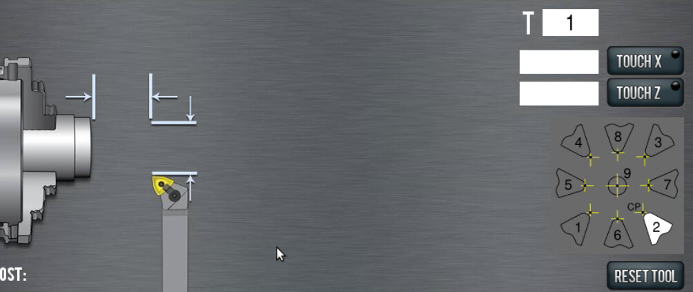
Because lathe tools can be oriented every which way, the control needs to know when a wear offset is applied which way to add or subtract the offset. We also use the tip orientation as a sanity check in conversational programming. The 8L is set up as a front toolpost lathe which means that positive x values are on the operator’s side of the spindle. If we see someone enter negative diameter values for a tool tip orientation that should be used from the front, we warn them in the conversational screens.
I hope that helps!
1 Like
Great information. This is just about how I thought the values in the table were meant to be used. However, my original question was, what are the negative and positive integer values in the Front Angle column of the 10001-10099 portion of the table? I never edit the table directly but always use the PP UI (the tool offset are too confusing otherwise), so the PP system enters these values when a tool is either defined, edited or reset using the UI.
As a programmer for over 50 years, I’m just nosey and have a need to know how things work internally.
@Jeffery_Babis I completely know what you mean. It’s been years since I touched that code so I had to do a little digging to make sure my recollection was correct. We used the I values in the registers from 10001-10099 to record which tool type image is associated with that tool. Because some of the tool images on the tool touch screen have the same tip orientation we couldn’t simply use tip orientation as the key for which tool was selected.
That make sense, since there are many more images of cutting tips than there are of the 9 tip orientations.