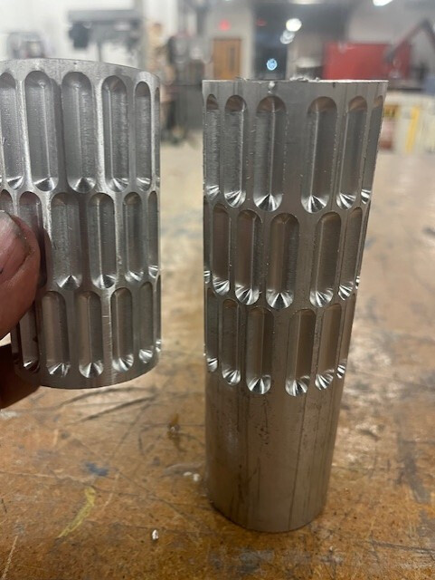
I am a hobbyist using the 4th axis on a PCNC1100 and cutting candy rollers. I’ve been frustrated that I can’t get a reproducible cut and I am at a loss as to why. I use the same G-code and everything else, but the cuts are inconsistent on the A-axis leading to misaligned rollers. See the pics of the first run and then the second. Any advice is welcome!
Have you centered your vice? It looks like the code was written for a different diameter stock. Smaller stock will move the indentations closer together and eliminate that gap at the end. Oversize stock results in what you have. The exact diameter will make them uniform only if your stock is perfectly centered or very close.
if it ‘skipped wouldn’t the rest of it be correct? This looks more like the spacing was to small all around and the left a gap. Like the 4th axis wasn’t turning enough each step through. The o ly thing I can think of that could have been different is I sped it up from 35% to 40%.
Yes. It was centered XYZ and A set to zero. If the cylinder was off size wouldn’t the angles still be the same but the depth of the cut off (too shallow).
Have you done some endurance testing? I would write a simple program to swing the 4th axis around and around and back again then check A0 with a dial indicator. Then do the same thing while applying friction to the system. See what kind of results you get. I would check for slippage from the chuck to the rotary and work piece to Chuck.
If you are cutting too hard you could be skipping the stepper but with the gear reduction on the rotary I wouldn’t expect that.
As others have mentioned, check for loose fitting wire connections
looks like slippage to me too since both parts differ. Are you getting a lot of chatter? That always used to cause stock to slither around in my old 4th and slotting with a ball-end mill pretty much guarantees the SFM is off somewhere. I’d mark the stock against some index points on the chuck and 4th to see if they move (Sharpie works well for this unless your coolant washes it off).
Is the one on the left made by you? As well as the one on the right?
Check both diameters. Looks like the one on the rights diameter is (1/3 difference of the in the wall thickness of the one on the left.)
I cut a lot of gears on my 4th axis and that’s what happens if the diameter is larger than the pitch used to calculate the program. Are you using a tail stock? Are the lines parallel on the x axis or are they converging? Another picture of both of them on the long axis would help.
Is the program your running a whole cad program or is it pieced together from conversational like I sometimes do for gears.
Also what material is that? Just wondering if it is coated after to make the candy not stick.
I agree with the notion that the 4th axis might be “slipping”, although I’d more specifically say that the stepper motor is missing steps or unable to drive against cutting forces depending on your toolpath.
I’d try a different strategy - guessing that you might be just going all-in with a ballnose endmill? Try roughing most of the pocket away with a smaller diameter endmill and then finishing with the ball.
Can you see what couples the stepper to the shaft? Maybe a sheared, loose woodruff key? Drive pin halfway out? Even if the diameters are different, pattern should be uniform.
It can’t be the G-code as I cut one perfectly and the second had the issue. Something has to be slipping or struggling with the stepping. The only thing I can think if that could have changed is setting the X-Y-Z point (but I don’t think that is the case) or I ran it a little faster the second time assuming it would work the same, but certainly wasn’t pushing it. Maybe that was enough to cause slippage.