I want to make a pulley for my 1100mx to increase the spindle speed to 30,000 rpm. I will be using sub 1mm carbide end mills in bt30 holders. My main question is can the bearings, bt30 holder and magnetic encoder handle the higher rpm? The torque placed on the tool and spindle are very low and I am cutting brass. If the above isn’t feasible what other solution can maintain the existing spindle runout at the higher rpm?
Hi Harold, I am no expert on spindle bearings but I would tentatively suggest what you are proposing is well beyond the engineering of these particular bearings. Take a look on YouTube at the video made by VC Edge, that’s Jayson Van Camp, where he talks about the bearings and limitations, and then fully dismantles and rebuilds one. There are numerous examples online of people saying they have had premature failure of the bearings, possibly because they have run the spindle at full speed with no careful warm up period, maybe in a cold garage or outhouse, who knows. You do need to take care of these bearings. When you start talking about 30,000rpm, you need things like ceramic bearings, and maybe even air cooling, as far as I know.
Also, may I suggest, if you try this, you take precautions and wear some protective gear, just in case of catastrophic failure of the casting. There is a lot of energy - don’t forget the speed term is squared in all the formulae I’ve ever seen!
1 Like
There are spindle speeders and auxiliary spindles that would probably be a better option. I’m with Steve, I don’t believe the grease packed cartridge in the Tormach would not last very long.
I have been looking at BT-30 spindle speeders. The manufacturers said they are really designed for the kind of work you are describing (not what I was looking for).
1 Like
Hello Dr. Harold,
The bearings in the spindle are not rated for those RPM’s, you can purchase bearings and rebuild the spindle to support higher speeds, however there is something more fundamental that will cause you an issue. The encoder feedback is expecting the same RPM’s that are being commanded. So when you spin the spindle at a different RPM than what is commanded at the control the encoder speed mismatch will cause the system to error out preventing you from running at those RPM’s.
If you wish to test this simply press the ‘Hi/Lo’ button on the screen (without changing the belt), type in 1000 RPM in the speed and press forward. You should see an error message telling you to check the belt position or something along those lines and it will stop.
If you were to go down this path I’m sure you can achieve 20,000 and with 1mm and for smaller bits those RPM’s are sufficient to do most everything without an issue. I’ve used other machines with a 24K limit and they milled with a 0.6mm endmill just fine at 20K to 24K that speed. Also keep in mind many of the tool holders are only rated for RPM’s around 20,000 some Max out at 30,000 so spinning faster will only multiply the runout error. Finally spindles with these rated RPM’s tend to have ceramic bearings so you will probably find with a few thousand investment you can replace with higher rated ball bearings but to my knowledge you will hit a mechanical barrier around 20,000 - 24,000 where you would have to create an entirely different spindle.
I really hope this helps you and assists in your project, please keep us posted on your progress.
1 Like
Now I am thinking side spindle. What about adding the side spindle onto the Z axis casting. I have a 24000rpm 2Kw cheap Chinese spindle with upgraded bearings. The weight is about 10 lbs. I am not sure what 10lbs off center would effect. I think I could make the mount with some eccentric bolts for squaring. I already have this spindle and siemens VFD from my sherline mill. What about that idea?
Sure would be better for your main spindle. Check out the casting designed to mount an auxiliary spindle 31891 - Universal Spindle Arm. Might be a quicker way to be up and running?
Another option for uber high speed spindle!
Top CNC Spindle - Motors & Live Tooling | Air Turbine Tools
These use air and mount in your bt tool holder!
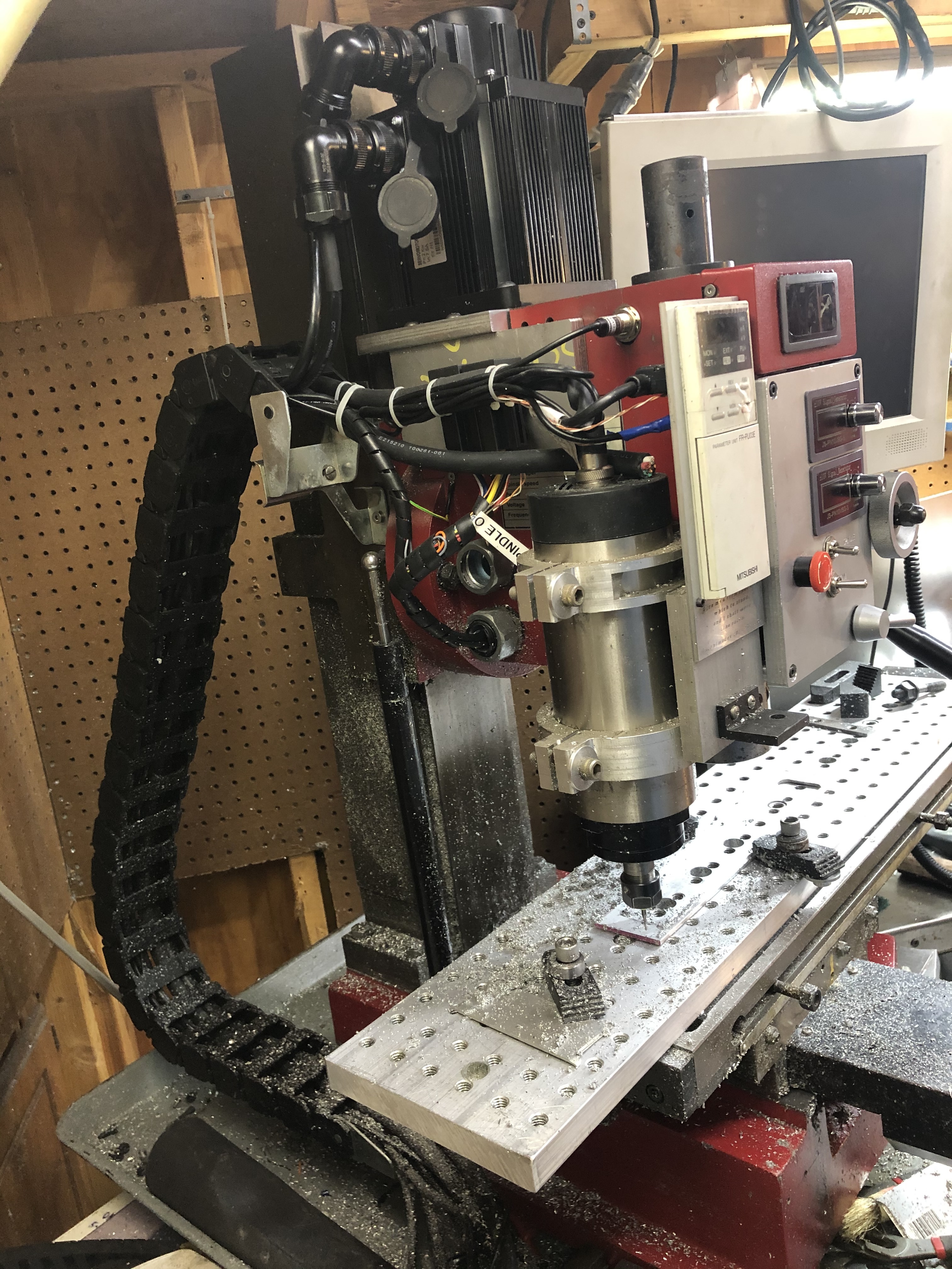
I mounted a 20k rpm spindle to the side of my main spindle for engraving and using .125 and smaller endmills.
1 Like
I think you are onto something as a better overall solution long term and if you mount it to the right side of the head you won’t obstruct the ATC for the main spindle in the future.
I chose this option. Now if I could just borrow someone’s mill to drill and tap a couple holes in the right side of my mill head. But seriously, eccentric mounting bolts or adjustable mount plate? Also anyone have any ideas about controlling a Siemens Sinamic v20 VFD via path pilot? Also I am thinking if I mount the second spindle just right I could rough on the left and finish on the right at the same time.
So there are a few things you need to tackle one is the Mounting of the spindle and the other is the mounting of the drive. Good news is with the MX you will have excess space in the cabinet where the X,Y,Z stepper drives would be on an M series machine, this is space where you can mount the Siemens Sinamic drive easily. Second is the mounting of the second spindle depends on the size of the spindle itself if it is round you can easily make a bracket that clamps onto the spindle nose while not interfering with an ATC. I would recommend a mounting plate with a threaded adjustment for finer precision. Also you can make an interlock reference plate so it will always mount in the same place. What this means is the interlock mounts to the spindle and stays there permanently so you can easily remove the secondary spindle and reinstall later with the same alignment.