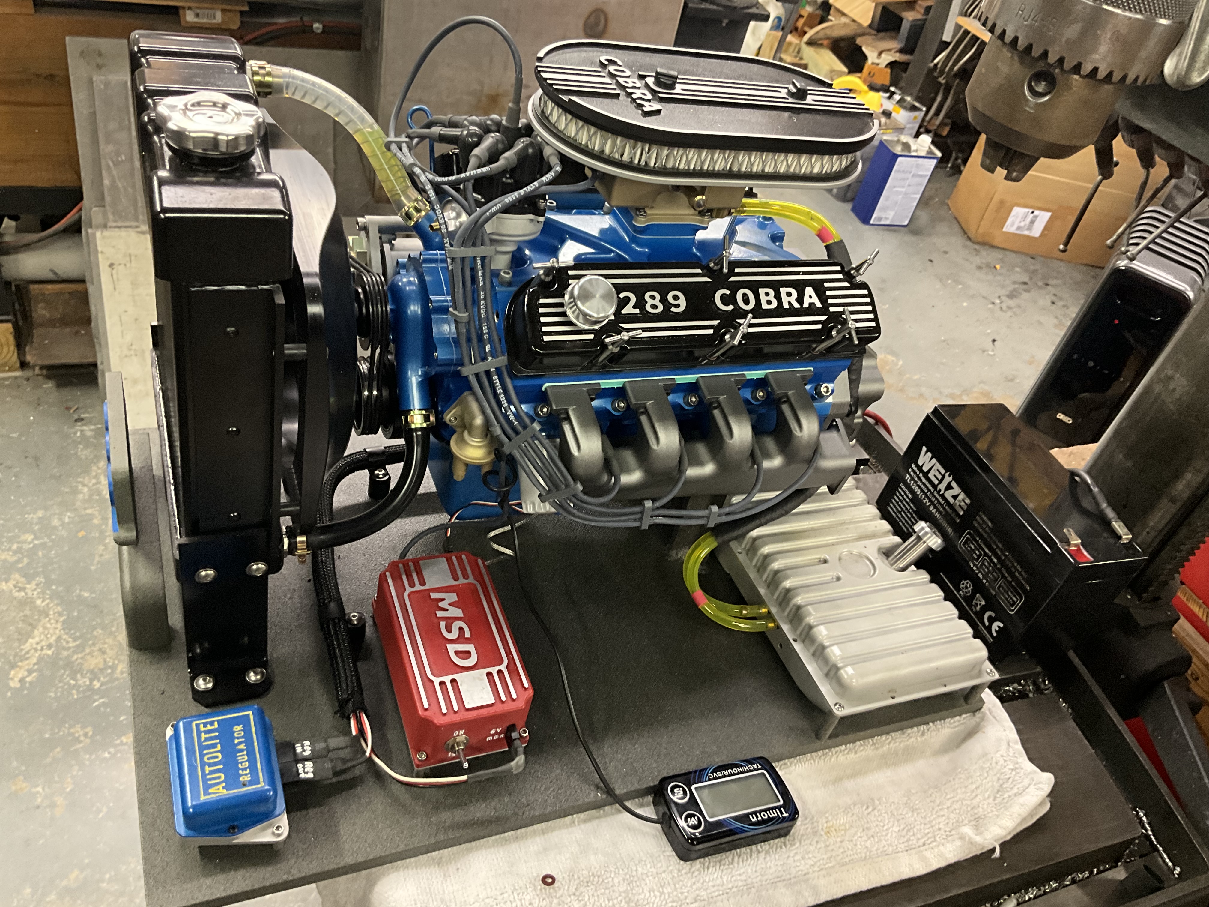
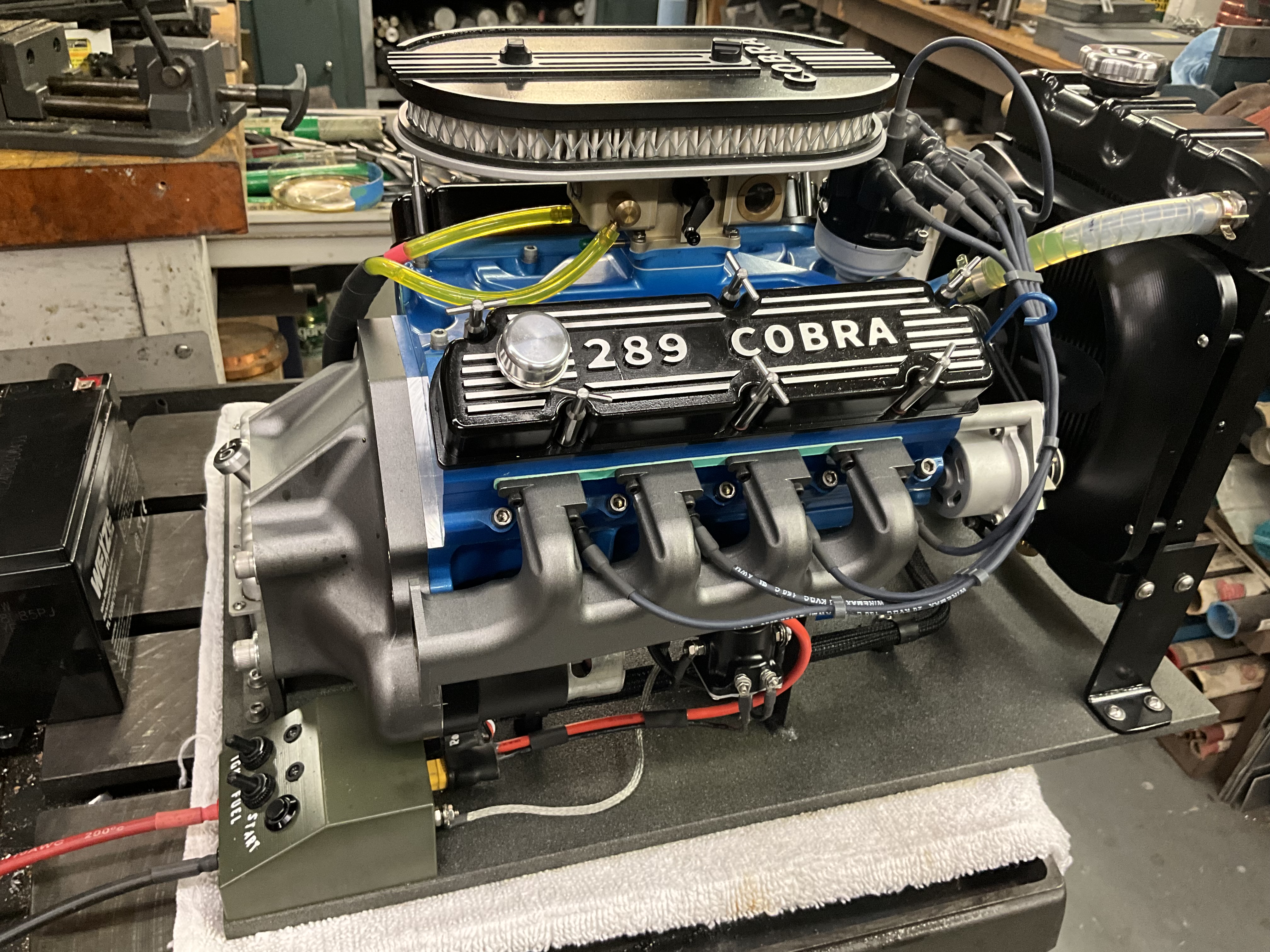
days ago and is a 1/3 scale running model of a Ford 289 HiPo engine. This 60’s era muscle car engine was found in the early Shelby Mustangs. My scaled model with its 22.5 cubic inch displacement is fully functional, liquid cooled, and runs on pump gasoline. It was machined from original plans on my twenty year old Tormach 1100, using Sprutcam 7 and Mach3 running on an ancient XP computer. Nearly everything but the spark plugs and fasteners was machined from materials purchased from a local recycling yard. The build was documented at:
with nearly 800 photos and lots of text. The carburetor is currently being fine tuned and a Youtube video will be available soon.
Holy cow! That is awesome work, thank you for sharing.
I am curious how you handled the various round parts like valves and things? Did you put a lathe tool in the vise and spin the material?
What is your process to get stock out of the scrap yard? Do they let you root around in the piles?
I could have cried the other day when my scrap yard wouldn’t sell me some 2" ss stock; there was 60ft of it.
Hi
The round parts like the valves, rings, and piston o.d.'s were done on a lathe. Those parts required tenths machining. and interpolating on the mill wasn’t practical. A lot of the non-critical rounds were machined on the mill though as I like hands-off machining.
A local recycling yard used to let people root around in their treasure piles. There were several machine shops in the area and they typical sent their drops there. For years I bought aluminum drops at 30-40 cents per pound and accumulated a lifetime of stock. Unfortunately, the business was purchased by another company who wasn’t willing to risk the liability of having people roaming on their property among all the working machinery. Just as well, though, as I didn’t have any more storage space. - Terry
I have followed your builds in great detail for over a decade now! You do some of the most detailed and well written write ups of your work anywhere on the internet. Merlin, Offy, V-twin and the radials have provided many hours of very interesting reading. It has been enjoyable to see your craft evolve and progress over the years.
Your name is even on the Sprutcam post for Tormach mill ! lol
Welcome to the Tormach forum btw.
And THANK YOU very much for all the time spent detailing your work and posting it online. I have learned so much from it over the many years.
I’m not sure if anyone went to the trouble of visiting the forum where the build of this engine was posted so I am adding a Youtube video link from the end of the build so those interested can see the engine actually running:
truly impressive.
I didn’t go through all 22 pages of posts on the forum, is the cooling in the head adequate? I have thoughts (dreams?) of doing an engine but the idea of hollow casting cylinder heads is not appealing.
Yes the cooling in the heads seems adequate. My last test run was at idle thru mid range and the full tank of gas lasted just under 12 minutes. At the end of the run an external contact measurement of the heads showed 154 degrees and the coolant temperature in the radiator was 155 degrees. The coolant capacity is 32 oz which is huge for a model engine. I drilled two long coolant passages through the heads as well as a number of cross passages through them. It takes several runs to evacuate the air from them but they do seem to be effective. There are also huge water jackets surrounding the cylinder liners. These were CNC’d blind on the Tormach using a modified Woodruff key slot cutter and were real nail biters. A good bit of time was spent developing an effective water pump and I went through a couple impeller designs before getting one that I was happy with. That pump really circulates the coolant with a vengeance Now whether the engine could do real work over some time without overheating is questionable, but that really wasn’t the goal of the build. - Terry
SLICK!
Now you have to built a hydroplane or something to stuff it in!
How did you do the cam? 4th axis?
I’m currently working on 4th tool paths including a cam shape. I’ve had the micro arc for a while now but haven’t worked with it but once when I first got it.
Have to see how tilt angle clearance works among other things. Modeled a practice part with features to try things out. I’ll give it a whirl soon.
I used the cam machining operation in Sprutcam to make the camshaft. (My version 7 is pretty old and I’m sure newer versions have more functionality. ) Since it is a long and skinny part I minimized stickout by doing just one lobe at a time as pulling the workpiece out of the 5C collet chucked into the horizontal 4th axis. as needed. The counterweights on the crankshaft were cut similarly. - Terry
There actually are no plans. I built SolidWorks models from various photographs, shop manuals and some full size engine drawings sent to me by a retired Ford machinist. - Terry
Wow, a lot of work.
Ok thanks, I’ll poke around.
The steam engine plans had dimensions in fractions and no tolerance, so I just made sure everything lined up and fit in cad, cut as close as I could, then opened things up as needed. Modeled the castings etc. They run on compressed air, about 30 psi, a nice little chug chug.
It was my first longer term mill project, good fun.